Installation Guide
Page 2
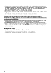
... for "Universal Plug and Play". • The Network Camera is referred to as "the camera" in this document. • The Setup CD-ROM is written for details regarding the camera's features. • Refer to as "BL-C160 only" in this document. • The camera illustrations in this document depict the BL-C160. • Model number suffixes ("A", "CE", and...
... for "Universal Plug and Play". • The Network Camera is referred to as "the camera" in this document. • The Setup CD-ROM is written for details regarding the camera's features. • Refer to as "BL-C160 only" in this document. • The camera illustrations in this document depict the BL-C160. • Model number suffixes ("A", "CE", and...
Installation Guide
Page 6
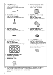
... need the following additional items to protect the camera from water … Sensor Range Cap (1 pc.) [BL-C160 Only] Order No. PNYCC160A Used to install and configure the camera. - PNWP3C160A Used to limit the sensor detection range … Setup CD-ROM (1 pc.) Order No. PQHG10765Z Used ... to protect the camera from water … Foam Strip (1pc.) Order No. a router 6 a PC (see the system requirements in the Important Information document) - 2 LAN cables (1 indoor cable and 1 outdoor cable) - … Safety Wire (1 pc.) Order No. PSHG1235Z Used to secure the camera when wall mounting it...
... need the following additional items to protect the camera from water … Sensor Range Cap (1 pc.) [BL-C160 Only] Order No. PNYCC160A Used to install and configure the camera. - PNWP3C160A Used to limit the sensor detection range … Setup CD-ROM (1 pc.) Order No. PQHG10765Z Used ... to protect the camera from water … Foam Strip (1pc.) Order No. a router 6 a PC (see the system requirements in the Important Information document) - 2 LAN cables (1 indoor cable and 1 outdoor cable) - … Safety Wire (1 pc.) Order No. PSHG1235Z Used to secure the camera when wall mounting it...
Installation Guide
Page 7
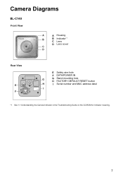
Camera Diagrams BL-C140 Front View A A Housing B B Indicator*1 C Lens D Lens cover C D Rear View E F E Safety wire hole F DATA/POWER IN G G Stand mounting hole H FACTORY DEFAULT RESET button H I Serial number and MAC address label I *1 See 1.1 Understanding the Camera Indicator in the Troubleshooting Guide on the CD-ROM for indicator meaning. 7
Camera Diagrams BL-C140 Front View A A Housing B B Indicator*1 C Lens D Lens cover C D Rear View E F E Safety wire hole F DATA/POWER IN G G Stand mounting hole H FACTORY DEFAULT RESET button H I Serial number and MAC address label I *1 See 1.1 Understanding the Camera Indicator in the Troubleshooting Guide on the CD-ROM for indicator meaning. 7
Installation Guide
Page 8
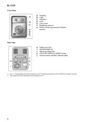
BL-C160 Front View A Housing A B Light C Indicator*1 B D Lens E Lens cover C F Brightness sensor*2 G Built-in sensor (pyroelectric infrared D sensor) E F G Rear View H I H Safety wire hole I DATA/POWER IN J Stand mounting hole K FACTORY DEFAULT RESET button L Serial number and MAC address label J K L *1 See 1.1 Understanding the Camera Indicator in the Troubleshooting Guide on the CD-ROM for indicator meaning. *2 The brightness sensor determines when the light turns on. 8
BL-C160 Front View A Housing A B Light C Indicator*1 B D Lens E Lens cover C F Brightness sensor*2 G Built-in sensor (pyroelectric infrared D sensor) E F G Rear View H I H Safety wire hole I DATA/POWER IN J Stand mounting hole K FACTORY DEFAULT RESET button L Serial number and MAC address label J K L *1 See 1.1 Understanding the Camera Indicator in the Troubleshooting Guide on the CD-ROM for indicator meaning. *2 The brightness sensor determines when the light turns on. 8

Installation Guide
Page 25
Adjusting Motion Detection Sensitivity The sensitivity of the motion detection can be adjusted to match the installation environment. For more information, see 2.10 Adjusting Motion Detection Sensitivity in the Operating Instructions on the CD-ROM. 25
Adjusting Motion Detection Sensitivity The sensitivity of the motion detection can be adjusted to match the installation environment. For more information, see 2.10 Adjusting Motion Detection Sensitivity in the Operating Instructions on the CD-ROM. 25
Installation Guide
Page 26
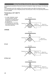
... About 5 m (16 feet 5 inches) Adjusting Sensor Sensitivity (BL-C160 Only) By adjusting the sensitivity of the camera location may be necessary to increase sensor sensitivity for the camera to make inaccurate detections. The temperature and other qualities of the ...built-in sensor, the detection range can cause the sensor to be operational. • Increasing sensor sensitivity can change in the Operating Instructions on the CD-ROM. For more information, see 2.9 Adjusting Sensor Sensitivity (BL...
... About 5 m (16 feet 5 inches) Adjusting Sensor Sensitivity (BL-C160 Only) By adjusting the sensitivity of the camera location may be necessary to increase sensor sensitivity for the camera to make inaccurate detections. The temperature and other qualities of the ...built-in sensor, the detection range can cause the sensor to be operational. • Increasing sensor sensitivity can change in the Operating Instructions on the CD-ROM. For more information, see 2.9 Adjusting Sensor Sensitivity (BL...