
Operating Instructions
Page 89
... Wireless Connection (BL-C131A Only) 5.2.1 Configuring the Camera for Wireless Connection (BL-C131A Only) Configure the camera for wireless access by your wireless router. • Even if your router supports the 802.11g standard (which is recommended. • If your wireless router uses MAC address filtering, enter the MAC address of the camera and the MAC address of...
... Wireless Connection (BL-C131A Only) 5.2.1 Configuring the Camera for Wireless Connection (BL-C131A Only) Configure the camera for wireless access by your wireless router. • Even if your router supports the 802.11g standard (which is recommended. • If your wireless router uses MAC address filtering, enter the MAC address of the camera and the MAC address of...

Operating Instructions
Page 93
... WIRED position. If you still cannot access the camera in wireless mode, see Page 119) and the MAC address of the camera to the WIRELESS position. 3. 5.2.2 Restarting the Camera in Wireless Mode (BL-C131A Only) 5.2.2 Restarting the Camera in Wireless Mode (BL-C131A Only) After you have configured the camera for about 5 minutes. Set the WIRELESS/WIRED switch...
... WIRED position. If you still cannot access the camera in wireless mode, see Page 119) and the MAC address of the camera to the WIRELESS position. 3. 5.2.2 Restarting the Camera in Wireless Mode (BL-C131A Only) 5.2.2 Restarting the Camera in Wireless Mode (BL-C131A Only) After you have configured the camera for about 5 minutes. Set the WIRELESS/WIRED switch...
Operating Instructions
Page 119
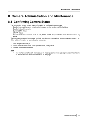
... MAC address - Dynamic DNS status - Click the [Maintenance] tab. 2. Note • See the Panasonic Network Camera support site (http://panasonic.co.jp/pcc/products/en/netwkcam) for troubleshooting assistance. 1. Detailed network information - Operating Instructions 119 8.1 Confirming Camera Status 8 Camera Administration and Maintenance 8.1 Confirming Camera Status... there have been any errors The information displayed on this page can confirm various camera status information on this information for details about the information displayed on the [Status] page such as you ...
... MAC address - Dynamic DNS status - Click the [Maintenance] tab. 2. Note • See the Panasonic Network Camera support site (http://panasonic.co.jp/pcc/products/en/netwkcam) for troubleshooting assistance. 1. Detailed network information - Operating Instructions 119 8.1 Confirming Camera Status 8 Camera Administration and Maintenance 8.1 Confirming Camera Status... there have been any errors The information displayed on this page can confirm various camera status information on this information for details about the information displayed on the [Status] page such as you ...

Operating Instructions
Page 120
... Wireless Status (BL-C131A Only) You can confirm various wireless information on the [Wireless Status] page such as you when the camera is no signal (0%) See the Panasonic Network Camera support site (http://panasonic.co.jp/pcc/products/en/netwkcam) for troubleshooting assistance. 1. The MAC address of the camera's wireless module (i.e., the MAC address used when the camera is displayed...
... Wireless Status (BL-C131A Only) You can confirm various wireless information on the [Wireless Status] page such as you when the camera is no signal (0%) See the Panasonic Network Camera support site (http://panasonic.co.jp/pcc/products/en/netwkcam) for troubleshooting assistance. 1. The MAC address of the camera's wireless module (i.e., the MAC address used when the camera is displayed...

Operating Instructions
Page 143
... drive of your network. Configuring a camera's network settings 1. Turn off the camera, then turn it is turned on and connected to the network. • If the desired camera is not displayed, you can find the camera by MAC Address], then enter the camera's MAC address. (The MAC address is not displayed..., confirm it on again. See Page 82 for details about each camera individually with 0080F0.) ...
... drive of your network. Configuring a camera's network settings 1. Turn off the camera, then turn it is turned on and connected to the network. • If the desired camera is not displayed, you can find the camera by MAC Address], then enter the camera's MAC address. (The MAC address is not displayed..., confirm it on again. See Page 82 for details about each camera individually with 0080F0.) ...
Installation Guide
Page 2
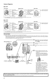
... J switch J LAN port K K DC IN jack L L MAC address label M M Serial number label *1 See 1.1 Understanding the Camera Indicator in the Troubleshooting Guide on the CD-ROM. N Tripod mounting hole O Wall mounting holes N O Connections Connect the camera to your router and to the power outlet as the main disconnect... of BL-C131 Router 4 Plug the AC adaptor into the power outlet. • The lens will pan and tilt when the camera is turned on. • Confirm that the AC outlet is installed near the product and is connected to the Panasonic Network Camera website (http://panasonic.co....
... J switch J LAN port K K DC IN jack L L MAC address label M M Serial number label *1 See 1.1 Understanding the Camera Indicator in the Troubleshooting Guide on the CD-ROM. N Tripod mounting hole O Wall mounting holes N O Connections Connect the camera to your router and to the power outlet as the main disconnect... of BL-C131 Router 4 Plug the AC adaptor into the power outlet. • The lens will pan and tilt when the camera is turned on. • Confirm that the AC outlet is installed near the product and is connected to the Panasonic Network Camera website (http://panasonic.co....
Setup Guide
Page 1
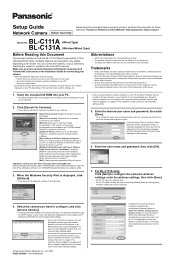
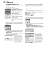
... [Select the program from Microsoft Corporation. • All other trademarks identified herein are included on the CDROM. Close your camera's MAC address label). 5. Enter the desired user name and password, then click [Save]. • Do not forget the user...and exits the Setup Program. Panasonic Network Camera Website: http://panasonic.net/pcc/ipcam/ BL-C111A Model No. (Wired Type) BL-C131A (Wireless/Wired Type) Before Reading this step. • BL-C131A users can confirm the model no . of the camera. printed on the camera model, network settings, etc. Confirm that ...
... [Select the program from Microsoft Corporation. • All other trademarks identified herein are included on the CDROM. Close your camera's MAC address label). 5. Enter the desired user name and password, then click [Save]. • Do not forget the user...and exits the Setup Program. Panasonic Network Camera Website: http://panasonic.net/pcc/ipcam/ BL-C111A Model No. (Wired Type) BL-C131A (Wireless/Wired Type) Before Reading this step. • BL-C131A users can confirm the model no . of the camera. printed on the camera model, network settings, etc. Confirm that ...

Service Manual
Page 2
...Parts List----------- 72 16.1. Pyroelectric Infrared Sensor Check 33 8.8. Diagnosis NG Check 36 8.12. How To Change MAC Address Label 38 8.16. Disassembly Instructions(BL-C131A 44 10 Maintenance 49 10.1. Waveform 62 14 Printed Circuit Board 65 14.1. Main Board (Bottom View... 8.11. Update Firmware 37 8.15. Main Board (Component View 65 14.2. Resetting the Camera 50 11.2. Lens Board (Component View 67 14.4. Lens Board (Bottom View 67 14.5. Replacement Parts List (BL-C111A 76 16.6. How to Replace a Flat Package IC 39 9 Disassembly and Assembly Instructions 40...
...Parts List----------- 72 16.1. Pyroelectric Infrared Sensor Check 33 8.8. Diagnosis NG Check 36 8.12. How To Change MAC Address Label 38 8.16. Disassembly Instructions(BL-C131A 44 10 Maintenance 49 10.1. Waveform 62 14 Printed Circuit Board 65 14.1. Main Board (Bottom View... 8.11. Update Firmware 37 8.15. Main Board (Component View 65 14.2. Resetting the Camera 50 11.2. Lens Board (Component View 67 14.4. Lens Board (Bottom View 67 14.5. Replacement Parts List (BL-C111A 76 16.6. How to Replace a Flat Package IC 39 9 Disassembly and Assembly Instructions 40...

Service Manual
Page 10
...Operating Power Supply: +3.3V Package: 54 pin TSOP Capacity: 64Mbit Outline of a Network Camera to the terminal on the Lens Board are accessed by I2C I /O) 1.2V (for CPU operation, MAC address and customer setup data. BL-C111A /BL-C131A 4 Technical Descriptions 4.1. RESET IC (IC106) Reset voltage: 2.9V Package:...9V. CMOS sensor (IC701) and Real Time Clock IC (IC3) on the IPV4 or IPV6 network using the network server function achieved by MII (Media Independent Interface) I /F. GPI0 • Motor (PAN/TILT) Operation • Clear Setting SW • Privacy Mode SW • I2C •...
...Operating Power Supply: +3.3V Package: 54 pin TSOP Capacity: 64Mbit Outline of a Network Camera to the terminal on the Lens Board are accessed by I2C I /O) 1.2V (for CPU operation, MAC address and customer setup data. BL-C111A /BL-C131A 4 Technical Descriptions 4.1. RESET IC (IC106) Reset voltage: 2.9V Package:...9V. CMOS sensor (IC701) and Real Time Clock IC (IC3) on the IPV4 or IPV6 network using the network server function achieved by MII (Media Independent Interface) I /F. GPI0 • Motor (PAN/TILT) Operation • Clear Setting SW • Privacy Mode SW • I2C •...

Service Manual
Page 16
...for a constant transmitter output level. 16 The RF Signal from the antenna through the Antenna Switch (IC502) and amplified at the built-in MAC Part by the CPU&MAC/BB/RFIC (IC601) is adjusted in the RFIC (IC601) for Frequency Converter and the Synthesizer generating the Receiving Local Signal. At the ... of the transmitting frequency band. The gain is converted to the RF Signal of the In-Phase(RxI) and Quadrature (RxQ) to the CPU&MAC/BB/RFIC(IC601) and, after being passed through the Antenna Switch (IC502). The baseband signal is input to output. BL-C111A /BL-C131A 4.2.
...for a constant transmitter output level. 16 The RF Signal from the antenna through the Antenna Switch (IC502) and amplified at the built-in MAC Part by the CPU&MAC/BB/RFIC (IC601) is adjusted in the RFIC (IC601) for Frequency Converter and the Synthesizer generating the Receiving Local Signal. At the ... of the transmitting frequency band. The gain is converted to the RF Signal of the In-Phase(RxI) and Quadrature (RxQ) to the CPU&MAC/BB/RFIC(IC601) and, after being passed through the Antenna Switch (IC502). The baseband signal is input to output. BL-C111A /BL-C131A 4.2.
Service Manual
Page 22
...user name and password you set here, otherwise you have a Panasonic BB-HGW700A Network Camera Control Unit, WEP settings will need to your network. • [About this step by configuring the corresponding camera settings to match the wireless settings of the printed documentation are using....exe found on your network. For BL-C131A Only: Click [Next] to configure the camera's wireless settings, enter the wireless settings, then click [Save]. • BL-C111A users can skip this step. • BL-C131A users can distinguish cameras by MAC address (see "Camera Diagrams" on page 2...
...user name and password you set here, otherwise you have a Panasonic BB-HGW700A Network Camera Control Unit, WEP settings will need to your network. • [About this step by configuring the corresponding camera settings to match the wireless settings of the printed documentation are using....exe found on your network. For BL-C131A Only: Click [Next] to configure the camera's wireless settings, enter the wireless settings, then click [Save]. • BL-C111A users can skip this step. • BL-C131A users can distinguish cameras by MAC address (see "Camera Diagrams" on page 2...

Service Manual
Page 36
Diagnosis NG Check When turning on the power, CPU makes a check using the self-diagnosis function. Check being able to the access to Diagnosis NG Check. • PAN/TILT operation • Pyroelectric Infrared Sensor • Video quality 8.11. BL-C111A /BL-C131A 8.10. When the self-diagnosis function of the device described below . The Inspection After The Repair Inspect the following items after the repair. • Confirm the status (specially MAC Address) refer to the device described below is NG turning on the power, CPU makes a check using the LED indicator red-blinks. 36
Diagnosis NG Check When turning on the power, CPU makes a check using the self-diagnosis function. Check being able to the access to Diagnosis NG Check. • PAN/TILT operation • Pyroelectric Infrared Sensor • Video quality 8.11. BL-C111A /BL-C131A 8.10. When the self-diagnosis function of the device described below . The Inspection After The Repair Inspect the following items after the repair. • Confirm the status (specially MAC Address) refer to the device described below is NG turning on the power, CPU makes a check using the LED indicator red-blinks. 36
Service Manual
Page 37
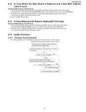
... the MAC Address of the RF board 1. BL-C111A/BL-C131A 8.12. BL-C131A only : Confirm that the WIRELESS/WIRED switch on the power after replacing the main board (after a old MAC has been written to the main board). Turn on . * Do not turn the power off during execution of the camera is not... turned on the power after replacing the RF board (after a new MAC has been written to WIRELESS. 2. Renew the MAC Address label. 8.13. Confirm that the WIRELESS/WIRED switch on . * Do not turn the power off , network failure or other causes. 37 Firmware Trouble Shouting The firmware updating is...
... the MAC Address of the RF board 1. BL-C111A/BL-C131A 8.12. BL-C131A only : Confirm that the WIRELESS/WIRED switch on the power after replacing the main board (after a old MAC has been written to the main board). Turn on . * Do not turn the power off during execution of the camera is not... turned on the power after replacing the RF board (after a new MAC has been written to WIRELESS. 2. Renew the MAC Address label. 8.13. Confirm that the WIRELESS/WIRED switch on . * Do not turn the power off , network failure or other causes. 37 Firmware Trouble Shouting The firmware updating is...

Service Manual
Page 38
Throw away the old main board. Make sure the old address cannot be used with the main board). How To Change MAC Address Label MAC address label caution When you replace the main board, you must also attach the new MAC address label(included with DDNS service.) 38 BL-C111A /BL-C131A 8.15. It cannot be reused. (If the MACaddress of the old main board is already registered via DDNS and thenused in a different camera, the camera cannot be seen. Attach the new MAC address label to the unit by placing over the old MAC address label.
Throw away the old main board. Make sure the old address cannot be used with the main board). How To Change MAC Address Label MAC address label caution When you replace the main board, you must also attach the new MAC address label(included with DDNS service.) 38 BL-C111A /BL-C131A 8.15. It cannot be reused. (If the MACaddress of the old main board is already registered via DDNS and thenused in a different camera, the camera cannot be seen. Attach the new MAC address label to the unit by placing over the old MAC address label.

Service Manual
Page 40
... Body. 40 Remove Main Board and I /O Board 1. Remove three Cable. 3. Attach the new MAC address label to the unit by placing over the old MAC address label. Disassembly Instructions(BL-C111A) 9.1.1. Make sure the old address cannot be used with the main board). Throw away the old...(If the MACaddress of the old main board is already registered via DDNS and thenused in a different camera, the camera cannot be seen. Remove two Screws (A). BL-C111A /BL-C131A 9 Disassembly and Assembly Instructions MAC address label caution hen you replace the main board, you must also attach the new...
... Body. 40 Remove Main Board and I /O Board 1. Remove three Cable. 3. Attach the new MAC address label to the unit by placing over the old MAC address label. Disassembly Instructions(BL-C111A) 9.1.1. Make sure the old address cannot be used with the main board). Throw away the old...(If the MACaddress of the old main board is already registered via DDNS and thenused in a different camera, the camera cannot be seen. Remove two Screws (A). BL-C111A /BL-C131A 9 Disassembly and Assembly Instructions MAC address label caution hen you replace the main board, you must also attach the new...

Service Manual
Page 51
...Regulator [IC101 ] Camera I/F JPEG,MPEG Ethernet MAC 1/6 VGA CMOS Sensor module +9V 20pin 3.3V [CN801] Regulator Clear Setting SW [SW802] SUB Board AMP & Filter Sensor [IC801] Power LED [ LED801 ] LENS SW [SW801] Main Board Motor Drive [IC402] TILT MOTOR CN401 PAN MOTOR 20pin [...CN201] RF Board(BL-C131A only) 16Mbit Flash [IC602] 64Mbit SDRAM BPF [IC603] LNA [Q501] Diversity Switch [IC502] +9V MAC/BBIC/RF [IC601] Power BPF AMP 20pin 40MHz [IC501] +9V [CN661] 3.3V & 1.8V Ethernet PHY DC -DC Converter [IC661] 25MHz BL-C111A/BL-C131A BLOCK DIAGRAM BL-C111A/BL-C131A
...Regulator [IC101 ] Camera I/F JPEG,MPEG Ethernet MAC 1/6 VGA CMOS Sensor module +9V 20pin 3.3V [CN801] Regulator Clear Setting SW [SW802] SUB Board AMP & Filter Sensor [IC801] Power LED [ LED801 ] LENS SW [SW801] Main Board Motor Drive [IC402] TILT MOTOR CN401 PAN MOTOR 20pin [...CN201] RF Board(BL-C131A only) 16Mbit Flash [IC602] 64Mbit SDRAM BPF [IC603] LNA [Q501] Diversity Switch [IC502] +9V MAC/BBIC/RF [IC601] Power BPF AMP 20pin 40MHz [IC501] +9V [CN661] 3.3V & 1.8V Ethernet PHY DC -DC Converter [IC661] 25MHz BL-C111A/BL-C131A BLOCK DIAGRAM BL-C111A/BL-C131A