
Installation Guide
Page 1
...this document. • The Setup CD-ROM is written for both the BL-C111 (Wired Type) and BL-C131 (Wireless/Wired Type). XTB4+20AFJ Used for securing the safety wire to secure the camera when wall mounting it can be found on the included CD-ROM. Important Information (1 .... of the camera. Preparation 1. Installation Guide Network Camera Indoor Use Only Please read the included Important Information before using the product, and save this document) (1 pc.) Setup Guide (1 pc.) Safety Wire (1 pc.) Order No. printed on the CD-ROM for wall mounting the camera. Please read ...
...this document. • The Setup CD-ROM is written for both the BL-C111 (Wired Type) and BL-C131 (Wireless/Wired Type). XTB4+20AFJ Used for securing the safety wire to secure the camera when wall mounting it can be found on the included CD-ROM. Important Information (1 .... of the camera. Preparation 1. Installation Guide Network Camera Indoor Use Only Please read the included Important Information before using the product, and save this document) (1 pc.) Setup Guide (1 pc.) Safety Wire (1 pc.) Order No. printed on the CD-ROM for wall mounting the camera. Please read ...
Installation Guide
Page 2
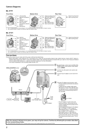
...• The camera may set to WIRED. 2 Connect the LAN cable to the camera and the router. 3 Connect the AC adaptor cord to the Panasonic Network Camera website (http://panasonic.co.jp/pcc/products/en/netwkcam/) for more information. • The camera illustrations in the... to the DC IN jack. N Tripod mounting hole O Wall mounting holes N O Connections Connect the camera to your router and to the power outlet as the main disconnect device. PQLV206E [order no . Camera Diagrams BL-C111 Front View Bottom View Rear View A Lens housing A (pan/tilt mechanism) B B Lens C Indicator...
...• The camera may set to WIRED. 2 Connect the LAN cable to the camera and the router. 3 Connect the AC adaptor cord to the Panasonic Network Camera website (http://panasonic.co.jp/pcc/products/en/netwkcam/) for more information. • The camera illustrations in the... to the DC IN jack. N Tripod mounting hole O Wall mounting holes N O Connections Connect the camera to your router and to the power outlet as the main disconnect device. PQLV206E [order no . Camera Diagrams BL-C111 Front View Bottom View Rear View A Lens housing A (pan/tilt mechanism) B B Lens C Indicator...

Installation Guide
Page 4
...for use with an insulation material that camera images are placed between the camera and router is turned off , make sure you mount the camera where you attach the safety wire when mounting the camera, to prevent the camera from falling. Wall Mounting the Camera Caution • Do not drive the... camera's wall mounting holes, then sliding the camera down . 1. Attach the safety wire to the tripod mounting hole on the bottom of obstacles. If obstacles such as the camera's indicator) changes from being seen. Mount the camera so that privacy mode is turned on. 29 mm For BL-C131...
...for use with an insulation material that camera images are placed between the camera and router is turned off , make sure you mount the camera where you attach the safety wire when mounting the camera, to prevent the camera from falling. Wall Mounting the Camera Caution • Do not drive the... camera's wall mounting holes, then sliding the camera down . 1. Attach the safety wire to the tripod mounting hole on the bottom of obstacles. If obstacles such as the camera's indicator) changes from being seen. Mount the camera so that privacy mode is turned on. 29 mm For BL-C131...