
Installation Guide
Page 1
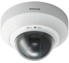
...Installation Procedure Overview The following items are explained in the USA and Puerto Rico BB-HCM527A Model No. (PoE Ready) Please read this document before proceeding. Setup Setting up the camera so that it can be found on the included CD-ROM. • This...camera. PQMD10111Z Used to secure the camera to secure the camera when mounting it can also connect the camera using a PC. • Refer to the Operating Instructions on the CD-ROM for installation. a LAN cable (CAT-5 straight cable) Option You can be accessed using the optional Panasonic BB-HCA3A AC Adaptor. The BB...
...Installation Procedure Overview The following items are explained in the USA and Puerto Rico BB-HCM527A Model No. (PoE Ready) Please read this document before proceeding. Setup Setting up the camera so that it can be found on the included CD-ROM. • This...camera. PQMD10111Z Used to secure the camera to secure the camera when mounting it can also connect the camera using a PC. • Refer to the Operating Instructions on the CD-ROM for installation. a LAN cable (CAT-5 straight cable) Option You can be accessed using the optional Panasonic BB-HCA3A AC Adaptor. The BB...

Installation Guide
Page 2
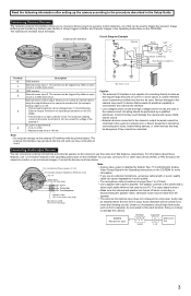
...when connecting a BB-HCM527A using a LAN cable (Cat-5 straight cable) as shown in the table below . 1 Connect a LAN cable to the camera and to the PoE hub. • Your PoE hub must be heard from the camera. If the indicator does not light green, see 1.2 Camera Indicator Issues ... your router and the power outlet as described below. • If using PoE (Power over Ethernet) Connect the camera to your router or to the Panasonic Network Camera website (http://panasonic.co.jp/pcc/products/en/netwkcam/) for the PoE hub's indicators to light. • The indicator display differs depending...
...when connecting a BB-HCM527A using a LAN cable (Cat-5 straight cable) as shown in the table below . 1 Connect a LAN cable to the camera and to the PoE hub. • Your PoE hub must be heard from the camera. If the indicator does not light green, see 1.2 Camera Indicator Issues ... your router and the power outlet as described below. • If using PoE (Power over Ethernet) Connect the camera to your router or to the Panasonic Network Camera website (http://panasonic.co.jp/pcc/products/en/netwkcam/) for the PoE hub's indicators to light. • The indicator display differs depending...
Installation Guide
Page 3
...interface has 6 terminals. The external I /O interface with a stereo audio cable similar to devices that can be used to trigger the camera's image buffering and transferring features (see 1.2.10 Audio Features in the Operating Instructions on the CDROM). • This terminal is input...customer-provided) may be no circumstance should high-level audio, such as shown below. Keep this input terminal. Connecting External Sensors The camera's external I /O interface is disabled by a qualified electrician. See 7.5 Controlling the Analog Video Output Signal in amplifier. All wiring ...
...interface has 6 terminals. The external I /O interface with a stereo audio cable similar to devices that can be used to trigger the camera's image buffering and transferring features (see 1.2.10 Audio Features in the Operating Instructions on the CDROM). • This terminal is input...customer-provided) may be no circumstance should high-level audio, such as shown below. Keep this input terminal. Connecting External Sensors The camera's external I /O interface is disabled by a qualified electrician. See 7.5 Controlling the Analog Video Output Signal in amplifier. All wiring ...
Installation Guide
Page 4
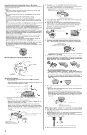
... this procedure. Insert anchors (customer-provided) into a soft material. Consult an authorized dealer for wiring cables Mounting the Camera 1. Cable hook 3. Place the camera on a concrete or mortar ceiling 1. Secure the ceiling plate to the ceiling about 110 mm (4 5/16 inches) from...firmly. Screws A (3 pcs.) (Length: 20 mm [13/16 inches], Body diameter: 4.0 mm [3/16 inches]) Mounting Reference Diagram (Bottom View) Camera Direction Ceiling Plate (4R5/11160inmcmhes) Necessary Installation Range 50 mm (1 15/16 inches) 30 mm (1 3/16 inches) Hole for mounting. Drive the ...
... this procedure. Insert anchors (customer-provided) into a soft material. Consult an authorized dealer for wiring cables Mounting the Camera 1. Cable hook 3. Place the camera on a concrete or mortar ceiling 1. Secure the ceiling plate to the ceiling about 110 mm (4 5/16 inches) from...firmly. Screws A (3 pcs.) (Length: 20 mm [13/16 inches], Body diameter: 4.0 mm [3/16 inches]) Mounting Reference Diagram (Bottom View) Camera Direction Ceiling Plate (4R5/11160inmcmhes) Necessary Installation Range 50 mm (1 15/16 inches) 30 mm (1 3/16 inches) Hole for mounting. Drive the ...


