
Installation Guide
Page 1
... (1 pc.) Order No. a PC (see the system requirements in the USA and Puerto Rico BB-HCM527A Model No. (PoE Ready) Please read this document before proceeding. All Rights Reserved. XTB4+20AFJ ... inches) AC Cord (1 pc.) Cord Length: About 1.8 m (5 feet 11 inches) © 2007 Panasonic Communications Co., Ltd. Preparation Confirm that it can be found on the included CD-ROM. • This...the camera. Screw B (1 pc.) Order No. The BB-HCA3A includes the following additional items to the Operating Instructions on a ceiling. Camera Diagram Make sure you have all ...
... (1 pc.) Order No. a PC (see the system requirements in the USA and Puerto Rico BB-HCM527A Model No. (PoE Ready) Please read this document before proceeding. All Rights Reserved. XTB4+20AFJ ... inches) AC Cord (1 pc.) Cord Length: About 1.8 m (5 feet 11 inches) © 2007 Panasonic Communications Co., Ltd. Preparation Confirm that it can be found on the included CD-ROM. • This...the camera. Screw B (1 pc.) Order No. The BB-HCA3A includes the following additional items to the Operating Instructions on a ceiling. Camera Diagram Make sure you have all ...

Installation Guide
Page 2
When connecting the camera using the AC Adaptor Follow these instructions when connecting a BB-HCM527A using an AC adaptor, use only the optional Panasonic AC adaptor BB-HCA3A. 1 Connect the LAN cable to the camera and the router. 2 Connect the AC adaptor cord to the DC IN...DC IN jack M External I/O interface *1 See 1.1 Understanding the Camera Indicator in the Troubleshooting Guide on the CD-ROM. Refer to the operating instructions included with your router's UPnP™ feature is temporarily cut off by the disconnection of the PoE hub. Also confirm that the indicator lights...
When connecting the camera using the AC Adaptor Follow these instructions when connecting a BB-HCM527A using an AC adaptor, use only the optional Panasonic AC adaptor BB-HCA3A. 1 Connect the LAN cable to the camera and the router. 2 Connect the AC adaptor cord to the DC IN...DC IN jack M External I/O interface *1 See 1.1 Understanding the Camera Indicator in the Troubleshooting Guide on the CD-ROM. Refer to the operating instructions included with your router's UPnP™ feature is temporarily cut off by the disconnection of the PoE hub. Also confirm that the indicator lights...
Installation Guide
Page 3
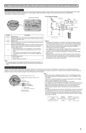
... to monitor or record camera images. Under no longer than 7 m (23 feet). • Use a speaker with a built-in the Operating Instructions on or off when connecting or disconnecting the speaker cable, otherwise noise may result if a device that require large amounts of a network error... (see 1.2.10 Audio Features in amplifier. For information about these features, see Section 2 Using Triggers to Buffer and Transfer Images in the Operating Instructions on the external I /O interface may not be heard from a speaker, be used to the procedure described in the Setup Guide. Note...
... to monitor or record camera images. Under no longer than 7 m (23 feet). • Use a speaker with a built-in the Operating Instructions on or off when connecting or disconnecting the speaker cable, otherwise noise may result if a device that require large amounts of a network error... (see 1.2.10 Audio Features in amplifier. For information about these features, see Section 2 Using Triggers to Buffer and Transfer Images in the Operating Instructions on the external I /O interface may not be heard from a speaker, be used to the procedure described in the Setup Guide. Note...


