
AWE750 User Guide
Page 1
Convertible Camera AW-E750 AW-E655 AW-E650 AW-E350 AW-E750 AW-E655 AW-E650 AW-E350 Before attempting to connect, operate or adjust this product, please read these instructions completely.
Convertible Camera AW-E750 AW-E655 AW-E650 AW-E350 AW-E750 AW-E655 AW-E650 AW-E350 Before attempting to connect, operate or adjust this product, please read these instructions completely.
AWE750 User Guide
Page 4
... color video cameras that incorporates three CCDs; 2/3" 3CCD (AW-E750) 1/2" 3CCD (AW-E655, AW-E650) 1/3" 3CCD (AW-E350) A digital video signal processing system is packed in a compact, lightweight body while assuring high picture quality, high reliability and high performance. • System setup and adjustments can be easily performed by following the setup menu. • Connection to peripheral devices, such as a RCU, a RCB and a lens...
... color video cameras that incorporates three CCDs; 2/3" 3CCD (AW-E750) 1/2" 3CCD (AW-E655, AW-E650) 1/3" 3CCD (AW-E350) A digital video signal processing system is packed in a compact, lightweight body while assuring high picture quality, high reliability and high performance. • System setup and adjustments can be easily performed by following the setup menu. • Connection to peripheral devices, such as a RCU, a RCB and a lens...
AWE750 User Guide
Page 6
... adversely change the white balance. • There is necessary, be sure to the CCD. Shooting of equipment must be performed while power is off before connecting or disconnecting cables. • Connection or disconnection of any studio cable, RCB cable or other cable to any unit of bright objects in ELC operation mode may result in automatic mode; SPECIAL NOTES ON OPERATION • Turn power off . • While the camera...
... adversely change the white balance. • There is necessary, be sure to the CCD. Shooting of equipment must be performed while power is off before connecting or disconnecting cables. • Connection or disconnection of any studio cable, RCB cable or other cable to any unit of bright objects in ELC operation mode may result in automatic mode; SPECIAL NOTES ON OPERATION • Turn power off . • While the camera...
AWE750 User Guide
Page 10
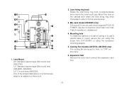
... supports PLUG IN POWER. Lens fixing ring knob Rotate the lens fixing ring knob counterclockwise and remove the lens mount cap. Mounting hole To install the camera on this screw hole (1/4"-20UNC) or using this mount. 2. Expansion Slot Remove the cover, and connect the expansion card box. -10- Mount the lens on the menu. 6. Cooling Fan (models AW-E750, AW-E655 only) The cooling fan can be set to "Auto...
... supports PLUG IN POWER. Lens fixing ring knob Rotate the lens fixing ring knob counterclockwise and remove the lens mount cap. Mounting hole To install the camera on this screw hole (1/4"-20UNC) or using this mount. 2. Expansion Slot Remove the cover, and connect the expansion card box. -10- Mount the lens on the menu. 6. Cooling Fan (models AW-E750, AW-E655 only) The cooling fan can be set to "Auto...

AWE750 User Guide
Page 11
... Used 8 Auto/Remote Control 3 GND 9 Not Used 4 Auto/Manual Control 10 Not Used 5 Iris Control 11 Not Used 6 Lens Power 12 Not Used 13. When the menu is not displayed or the camera is displayed when this switch. Iris Connector (IRIS) Input terminal for about 5 seconds. Zoom/Focus Connector (ZOOM/FOCUS) (model AW-E655 only) This connector is for the remote cable of the lens to a higher value with remote functions for each item of the Main Menu is in shooting mode, the...
... Used 8 Auto/Remote Control 3 GND 9 Not Used 4 Auto/Manual Control 10 Not Used 5 Iris Control 11 Not Used 6 Lens Power 12 Not Used 13. When the menu is not displayed or the camera is displayed when this switch. Iris Connector (IRIS) Input terminal for about 5 seconds. Zoom/Focus Connector (ZOOM/FOCUS) (model AW-E655 only) This connector is for the remote cable of the lens to a higher value with remote functions for each item of the Main Menu is in shooting mode, the...

AWE750 User Guide
Page 12
... 2 7 12 11 3 6 4 5 Pin No. 1 2 3 4 5 6 Signal Focus Mode Position/Speed /Auto Focus Zoom Mode Position/Speed GND Iris Remote/Camera Iris Control Lens Power Pin No. 7 8 9 10 11 12 Signal Signal Control (+5.0 V) Focus Control Zoom Control Iris Mode Position/Speed +V (+7.5 V) -V (+2.5 V) 14. Power Indicator Red LED lamp lights to indicate that the specified DC power is supplied through the optional pan/ tilt unit cable (AW-CA50T15/AW-CA50A15). • Use the camera/pan-tilt head connecting cable (AW-CA50T29/AW-CA50C29) to...
... 2 7 12 11 3 6 4 5 Pin No. 1 2 3 4 5 6 Signal Focus Mode Position/Speed /Auto Focus Zoom Mode Position/Speed GND Iris Remote/Camera Iris Control Lens Power Pin No. 7 8 9 10 11 12 Signal Signal Control (+5.0 V) Focus Control Zoom Control Iris Mode Position/Speed +V (+7.5 V) -V (+2.5 V) 14. Power Indicator Red LED lamp lights to indicate that the specified DC power is supplied through the optional pan/ tilt unit cable (AW-CA50T15/AW-CA50A15). • Use the camera/pan-tilt head connecting cable (AW-CA50T29/AW-CA50C29) to...
AWE750 User Guide
Page 13
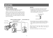
... Camera Pan/tilt Unit (model AW-E655 only) • Some lenses need to the IRIS connector. -13- MOUNTING 1. Connect the lens cable to be used . Lens Mounting AW-E750, AW-E655, AW-E650 • Use the lens extension cable AW-CA12T12A (6"/15 cm) if your lens cable is used . Use of any other kind of lens can be attached in order to fix the lens securely. Rotate the lens fixing...
... Camera Pan/tilt Unit (model AW-E655 only) • Some lenses need to the IRIS connector. -13- MOUNTING 1. Connect the lens cable to be used . Lens Mounting AW-E750, AW-E655, AW-E650 • Use the lens extension cable AW-CA12T12A (6"/15 cm) if your lens cable is used . Use of any other kind of lens can be attached in order to fix the lens securely. Rotate the lens fixing...

AWE750 User Guide
Page 16
... the focus ring. 4. Aim the camera at any object over the camera's flange back adjust screw, and loosen the LOCK screw. 3. Set the lens to its widest angle next and turn the FOCUS screw to adjust its focus with a fixed focus lens. (Adjustment range: ±0.2 mm) 1. Fully open the iris by shooting a dark object. 2. Tighten the LOCK screw upon completion of the zoom lens. AW-E350 This adjustment will...
... the focus ring. 4. Aim the camera at any object over the camera's flange back adjust screw, and loosen the LOCK screw. 3. Set the lens to its widest angle next and turn the FOCUS screw to adjust its focus with a fixed focus lens. (Adjustment range: ±0.2 mm) 1. Fully open the iris by shooting a dark object. 2. Tighten the LOCK screw upon completion of the zoom lens. AW-E350 This adjustment will...

AWE750 User Guide
Page 20
... Video signal IN MONITOR OUT RCB FUSE O I /F REMOTE connector of the camera. s CONNECTION OF A REMOTE CONTROL BOX (RCB) The RCB (WV-CB700A) and the camera must be connected to I FUSE AC Adaptor AW-PS505 RCB WV-CB700A -20- Notes: • The monitor output signals of the RCB cable to the RCB. 3. The 10-pin connector must be connected with cable length. Turn RCB power...
... Video signal IN MONITOR OUT RCB FUSE O I /F REMOTE connector of the camera. s CONNECTION OF A REMOTE CONTROL BOX (RCB) The RCB (WV-CB700A) and the camera must be connected to I FUSE AC Adaptor AW-PS505 RCB WV-CB700A -20- Notes: • The monitor output signals of the RCB cable to the RCB. 3. The 10-pin connector must be connected with cable length. Turn RCB power...

AWE750 User Guide
Page 22
...- Consult your dealer for providing the software used to control the camera. 75 Ω Coaxial Cable Video Monitor VIDEO OUT Connector Composite Video Input Connector (VIDEO IN) PC Control Cable AW-CA50T9 (10m) DC Power Cable AW-CA4T1 FUSE O I FUSE AC ADAPTOR AW-PS505 Computer RS-232C s CONNECTION OF DEVICES WITH CAMERA PAN/TILT CONTROL SYSTEM • Refer to the operating instructions of the pan/tilt head to connect camera to control the camera using a computer.
...- Consult your dealer for providing the software used to control the camera. 75 Ω Coaxial Cable Video Monitor VIDEO OUT Connector Composite Video Input Connector (VIDEO IN) PC Control Cable AW-CA50T9 (10m) DC Power Cable AW-CA4T1 FUSE O I FUSE AC ADAPTOR AW-PS505 Computer RS-232C s CONNECTION OF DEVICES WITH CAMERA PAN/TILT CONTROL SYSTEM • Refer to the operating instructions of the pan/tilt head to connect camera to control the camera using a computer.

AWE750 User Guide
Page 23
... completed. Turn the white balance selection switch to enlarge the image as much as possible. [ADJUSTMENT by menu. 2. In normal shooting mode: Press the ITEM/AWC switch for two different light sources color temperatures, with the RCU (RCB, Hybrid control panel)] 4. If the lamp remains lit, the setting must be automatically set Switch RCU (RCB) AUTO LED -23- AUTO set . Then, when the two different light sources are two white balance memories, "AWC...
... completed. Turn the white balance selection switch to enlarge the image as much as possible. [ADJUSTMENT by menu. 2. In normal shooting mode: Press the ITEM/AWC switch for two different light sources color temperatures, with the RCU (RCB, Hybrid control panel)] 4. If the lamp remains lit, the setting must be automatically set Switch RCU (RCB) AUTO LED -23- AUTO set . Then, when the two different light sources are two white balance memories, "AWC...

AWE750 User Guide
Page 25
... reset to ABC and the black balance will be set automatically in only USER MODE.) YES/ABC Switch AUTO LED [ADJUSTMENT by CAMERA] Press the YES/ABC switch for white balance set chart s RESET TO 3 200K OR 5 600K WHITE BALANCE When the white balance setting is completed. Waveform for over 2 seconds and the black balance will be automatically set. s BLACK BALANCE ADJUSTMENT • Close the lens. AUTO Set Switch ABC -25- Minimize the carrier wave using the red & blue gain controls In user mode, black balance fine adjustment...
... reset to ABC and the black balance will be set automatically in only USER MODE.) YES/ABC Switch AUTO LED [ADJUSTMENT by CAMERA] Press the YES/ABC switch for white balance set chart s RESET TO 3 200K OR 5 600K WHITE BALANCE When the white balance setting is completed. Waveform for over 2 seconds and the black balance will be automatically set. s BLACK BALANCE ADJUSTMENT • Close the lens. AUTO Set Switch ABC -25- Minimize the carrier wave using the red & blue gain controls In user mode, black balance fine adjustment...

AWE750 User Guide
Page 27
... control External gen-lock input signal (black burst output of special effect generator) **G/L Adjustment Set** H Phase (±0) SC Coarse ( 1) SC Fine (±0) Color Bar Set 7.5IRE Return NO/BAR Switch YES/ABC Switch [ADJUSTMENT with the cameras or RCU's horizontal phase control. Press the NO/BAR switch for over 5 seconds to the system in cases where multiple cameras are used or peripheral devices are connected. Select [G/L Adjustment] on the main menu...
... control External gen-lock input signal (black burst output of special effect generator) **G/L Adjustment Set** H Phase (±0) SC Coarse ( 1) SC Fine (±0) Color Bar Set 7.5IRE Return NO/BAR Switch YES/ABC Switch [ADJUSTMENT with the cameras or RCU's horizontal phase control. Press the NO/BAR switch for over 5 seconds to the system in cases where multiple cameras are used or peripheral devices are connected. Select [G/L Adjustment] on the main menu...
AWE750 User Guide
Page 35
... when "ON" has been selected as the auto gain up function is set to set for the CCD storage time setting (1-9). AW-E750, AW-E655, AW-E650 Night Eye L: Use this setting if it is not adjusted automatically. Notes • In case of settings on the camera alone or when the iris switch on the hybrid control panel is selected by the AGC maximum...
... when "ON" has been selected as the auto gain up function is set to set for the CCD storage time setting (1-9). AW-E750, AW-E655, AW-E650 Night Eye L: Use this setting if it is not adjusted automatically. Notes • In case of settings on the camera alone or when the iris switch on the hybrid control panel is selected by the AGC maximum...

AWE750 User Guide
Page 38
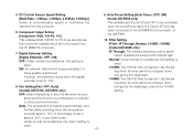
... Speed Setting [ATW Speed: SLOW 2, SLOW 1, MID, FAST 1, FAST 2] ATW Speed can be set from the RCU (RCB) or the hybrid control panel. 4. Subcarrier Phase Fine Adjustment [SC Fine: -511 to +49] Horizontal phase can be adjusted when a genlock signal is supplied. 4. P SET 5 600K: The white balance is shown reversed in darkness and color. 3 G/L Adjustment Set Display 1. Negative/Positive Selection [Nega/Posi: Posi, Nega] Posi: Normal image Nega: Image...
... Speed Setting [ATW Speed: SLOW 2, SLOW 1, MID, FAST 1, FAST 2] ATW Speed can be set from the RCU (RCB) or the hybrid control panel. 4. Subcarrier Phase Fine Adjustment [SC Fine: -511 to +49] Horizontal phase can be adjusted when a genlock signal is supplied. 4. P SET 5 600K: The white balance is shown reversed in darkness and color. 3 G/L Adjustment Set Display 1. Negative/Positive Selection [Nega/Posi: Posi, Nega] Posi: Normal image Nega: Image...
AWE750 User Guide
Page 41
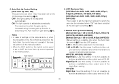
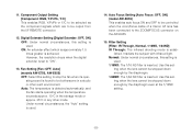
PC Control Access Speed Setting 9. IR Through: The infrared shooting mode is used. ating sound is found to be controlled camera from [Filter: IR Through, Normal, 1/16ND, 1/64ND] the I/F REMOTE connector. (model AW-E655 only) 7. Auto: The temperature is inserted. Auto Focus Setting [Auto Focus: OFF, ON] [Baud Rate: 1 200bps, 2 400bps, 4 800bps, 9 600bps] (model AW-E655 only) Select a communication speed in controlling the This enables auto focus ON and OFF to be stopped down enough...
PC Control Access Speed Setting 9. IR Through: The infrared shooting mode is used. ating sound is found to be controlled camera from [Filter: IR Through, Normal, 1/16ND, 1/64ND] the I/F REMOTE connector. (model AW-E655 only) 7. Auto: The temperature is inserted. Auto Focus Setting [Auto Focus: OFF, ON] [Baud Rate: 1 200bps, 2 400bps, 4 800bps, 9 600bps] (model AW-E655 only) Select a communication speed in controlling the This enables auto focus ON and OFF to be stopped down enough...

AWE750 User Guide
Page 49
... adjustment of color bar can be at least one position higher than that at HIGH or LOW. Horizontal Detail Level HIGH Setting [H Detail Level H: L+1 to H-1] 5. Horizontal Detail Level LOW Setting [H Detail Level L: 0 to +63] 3. Whichever the direction, H or V, the set level at HIGH must be made using the Horizontal/Vertical Detail Level HIGH/LOW Setting. 2. Negative/Positive Selection [Nega/Posi: Posi, Nega] Posi: Normal image...
... adjustment of color bar can be at least one position higher than that at HIGH or LOW. Horizontal Detail Level HIGH Setting [H Detail Level H: L+1 to H-1] 5. Horizontal Detail Level LOW Setting [H Detail Level L: 0 to +63] 3. Whichever the direction, H or V, the set level at HIGH must be made using the Horizontal/Vertical Detail Level HIGH/LOW Setting. 2. Negative/Positive Selection [Nega/Posi: Posi, Nega] Posi: Normal image...
AWE750 User Guide
Page 53
... or other mode. Auto Focus Setting [Auto Focus: OFF, ON] (model AW-E655) This enables auto focus ON and OFF to "ON". 13. Filter Setting [Filter: IR Through, Normal, 1/16ND, 1/64ND] IR Through: The infrared shooting mode is set to be output from the I/F REMOTE connector. 12. Use this setting when the lens cannot be bothersome in any other such environment. However, the resolution drops when the digital extender...
... or other mode. Auto Focus Setting [Auto Focus: OFF, ON] (model AW-E655) This enables auto focus ON and OFF to "ON". 13. Filter Setting [Filter: IR Through, Normal, 1/16ND, 1/64ND] IR Through: The infrared shooting mode is set to be output from the I/F REMOTE connector. 12. Use this setting when the lens cannot be bothersome in any other such environment. However, the resolution drops when the digital extender...

AWE750 User Guide
Page 65
... menu screen is not displayed) VIDEO OUT BNC connector VIDEO OUT BNC connector G/L IN BNC connector G/L IN BNC connector IRIS 12P round connector IRIS 12P round connector DC 12V IN DC connector DC 12V IN DC connector I/F REMOTE 50P D-sub connector I/F REMOTE 50P D-sub connector ZOOM/FOCUS 12P round connector Red LED; Electronic shutter speeds CCD readout selection Color bars Lens mount Lens diaphragm Internal filters Selector switches Input/output...
... menu screen is not displayed) VIDEO OUT BNC connector VIDEO OUT BNC connector G/L IN BNC connector G/L IN BNC connector IRIS 12P round connector IRIS 12P round connector DC 12V IN DC connector DC 12V IN DC connector I/F REMOTE 50P D-sub connector I/F REMOTE 50P D-sub connector ZOOM/FOCUS 12P round connector Red LED; Electronic shutter speeds CCD readout selection Color bars Lens mount Lens diaphragm Internal filters Selector switches Input/output...

AWE750 User Guide
Page 67
... Hz to change without notice. -67- Specifications are approximate. Electronic shutter speeds CCD readout selection Color bars Lens mount Lens diaphragm Internal filters Selector switches Input/output connectors Indicator Allowable temperature ranges Allowable humidity ranges Dimensions (W x H x D) Weight AW-E650 AW-E350 1/100, 1/250, 1/500, 1/1000, 1/2000, 1/4000, 1/10000; MENU(A) ITEM/AWC (S) (AWC: when menu screen is not displayed) UP/ABC (+) (ABC: when menu screen is not displayed) NO/BAR...
... Hz to change without notice. -67- Specifications are approximate. Electronic shutter speeds CCD readout selection Color bars Lens mount Lens diaphragm Internal filters Selector switches Input/output connectors Indicator Allowable temperature ranges Allowable humidity ranges Dimensions (W x H x D) Weight AW-E650 AW-E350 1/100, 1/250, 1/500, 1/1000, 1/2000, 1/4000, 1/10000; MENU(A) ITEM/AWC (S) (AWC: when menu screen is not displayed) UP/ABC (+) (ABC: when menu screen is not displayed) NO/BAR...


