
AWE350 User Guide
Page 4
...) A digital video signal processing system is packed in a compact, lightweight body while assuring high picture quality, high reliability and high performance. • System setup and adjustments can be easily performed by following the setup menu. • Connection to peripheral devices, such as a RCU, a RCB and a lens and the camera pan/tilt unit enables a wide variation of system configurations. • Option cards may also be installed. ❈...
...) A digital video signal processing system is packed in a compact, lightweight body while assuring high picture quality, high reliability and high performance. • System setup and adjustments can be easily performed by following the setup menu. • Connection to peripheral devices, such as a RCU, a RCB and a lens and the camera pan/tilt unit enables a wide variation of system configurations. • Option cards may also be installed. ❈...

AWE350 User Guide
Page 7
.... Do not unnecessarily turn the camera power on or not. • Do not expose the camera or Remote Control Unit (RCU) to rain or moisture, and do not leave the lens mount hole uncovered. • Do not touch the surface of abrasive detergents when cleaning the camera body. • Do not aim the camera toward the sun, no user-serviceable parts inside. • Do...
.... Do not unnecessarily turn the camera power on or not. • Do not expose the camera or Remote Control Unit (RCU) to rain or moisture, and do not leave the lens mount hole uncovered. • Do not touch the surface of abrasive detergents when cleaning the camera body. • Do not aim the camera toward the sun, no user-serviceable parts inside. • Do...

AWE350 User Guide
Page 8
... turn the power off and have the unit checked by placing the lens cap over when the camera is adequate ventilation. -8- If the lens is not installed, protect the surface of the prism by placing the body cap into the lens mount hole. • Use a mild blower or lens cleaning tissue designed for coated lenses, to clean the surface of spot lights...
... turn the power off and have the unit checked by placing the lens cap over when the camera is adequate ventilation. -8- If the lens is not installed, protect the surface of the prism by placing the body cap into the lens mount hole. • Use a mild blower or lens cleaning tissue designed for coated lenses, to clean the surface of spot lights...
AWE350 User Guide
Page 10
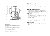
... lens mount cap. Use the microphone which supports PLUG IN POWER. Cooling Fan (models AW-E750, AW-E655 only) The cooling fan can be set to "Auto" or "OFF" on the camera and rotate the lens fixing ring knob clockwise in order to use a pan/tilt head or tripod, secure the unit using the accessory mounting adaptor. 5. Expansion Slot Remove the cover, and connect the expansion card box. -10- Mic Jack (model...
... lens mount cap. Use the microphone which supports PLUG IN POWER. Cooling Fan (models AW-E750, AW-E655 only) The cooling fan can be set to "Auto" or "OFF" on the camera and rotate the lens fixing ring knob clockwise in order to use a pan/tilt head or tripod, secure the unit using the accessory mounting adaptor. 5. Expansion Slot Remove the cover, and connect the expansion card box. -10- Mic Jack (model...
AWE350 User Guide
Page 11
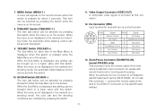
.... When the menu is not displayed or the camera is on the pan/tilt head instead. -11- Signal Pin No. connect the remote cable of the lens to be selected by pressing the switch. 11. While the Sub Menu is displayed any setting can be mounted on the screen. Signal 1 Return Control 7 Iris Follow 2 Not Used 8 Auto/Remote Control 3 GND 9 Not Used 4 Auto/Manual Control 10 Not Used 5 Iris Control 11 Not Used 6 Lens Power 12 Not Used 13. NO...
.... When the menu is not displayed or the camera is on the pan/tilt head instead. -11- Signal Pin No. connect the remote cable of the lens to be selected by pressing the switch. 11. While the Sub Menu is displayed any setting can be mounted on the screen. Signal 1 Return Control 7 Iris Follow 2 Not Used 8 Auto/Remote Control 3 GND 9 Not Used 4 Auto/Manual Control 10 Not Used 5 Iris Control 11 Not Used 6 Lens Power 12 Not Used 13. NO...

AWE350 User Guide
Page 12
...Pin No. 1 2 3 4 5 6 Signal Focus Mode Position/Speed /Auto Focus Zoom Mode Position/Speed GND Iris Remote/Camera Iris Control Lens Power Pin No. 7 8 9 10 11 12 Signal Signal Control (+5.0 V) Focus Control Zoom Control Iris Mode Position/Speed +V (+7.5 V) -V (+2.5 V) 14. Connect this connector when the camera is supplied to the convertible camera. 15. I/F Remote Connector (I/F REMOTE) Input terminal dedicated to control signals from slipping out. 19. DC 12 V Input Connector (DC 12V IN) 12 V DC is connected through the optional DC power supply cable (AW-CA4T1). (Recommended AC...
...Pin No. 1 2 3 4 5 6 Signal Focus Mode Position/Speed /Auto Focus Zoom Mode Position/Speed GND Iris Remote/Camera Iris Control Lens Power Pin No. 7 8 9 10 11 12 Signal Signal Control (+5.0 V) Focus Control Zoom Control Iris Mode Position/Speed +V (+7.5 V) -V (+2.5 V) 14. Connect this connector when the camera is supplied to the convertible camera. 15. I/F Remote Connector (I/F REMOTE) Input terminal dedicated to control signals from slipping out. 19. DC 12 V Input Connector (DC 12V IN) 12 V DC is connected through the optional DC power supply cable (AW-CA4T1). (Recommended AC...
AWE350 User Guide
Page 14
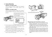
... camera, lens, connection cables, etc., fix the camera firmly in position using the safety chain and the mounting screws to the bottom panel of the camera. If the camera cannot be securely fixed, mount the camera on any mounting or other pan/tilt head, check that the mounting adaptor is attached the right way round. OWhen attaching the camera on a mounting bracket or the like with the supplied rubber sheet between the camera...
... camera, lens, connection cables, etc., fix the camera firmly in position using the safety chain and the mounting screws to the bottom panel of the camera. If the camera cannot be securely fixed, mount the camera on any mounting or other pan/tilt head, check that the mounting adaptor is attached the right way round. OWhen attaching the camera on a mounting bracket or the like with the supplied rubber sheet between the camera...

AWE350 User Guide
Page 18
... service personnel or system installers. s CONNECTION OF DEVICE WITH A COMPOSITE INPUT CONNECTOR • Connection to any servicing to qualified service personnel. CONNECTIONS Caution: The connection and installation should be through the VIDEO OUT Connector. • Power supply to the camera must be made through the optional DC power supply Cable AW-CA4T1. • For DC power supply, use the optional AC adaptor AW-PS505. 75 Ω coaxial cable VIDEO OUT Connector VIDEO IN Video monitor FUSE DC Power supply Cable...
... service personnel or system installers. s CONNECTION OF DEVICE WITH A COMPOSITE INPUT CONNECTOR • Connection to any servicing to qualified service personnel. CONNECTIONS Caution: The connection and installation should be through the VIDEO OUT Connector. • Power supply to the camera must be made through the optional DC power supply Cable AW-CA4T1. • For DC power supply, use the optional AC adaptor AW-PS505. 75 Ω coaxial cable VIDEO OUT Connector VIDEO IN Video monitor FUSE DC Power supply Cable...
AWE350 User Guide
Page 19
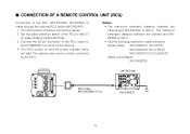
...-RC700A is 300 m. s CONNECTION OF A REMOTE CONTROL UNIT (RCU) Connection to the RCU (WV-RC700A, WV-RC550) is 100 m. • Use the following options for cable extension. Notes: • The maximum extension distance between the camera and WVRC550 is made through the optional RCU cable AW-CA50A26. 1. Turn RCU power on and the power indicator lamp will light. Set the cable selection switch of the RCU...
...-RC700A is 300 m. s CONNECTION OF A REMOTE CONTROL UNIT (RCU) Connection to the RCU (WV-RC700A, WV-RC550) is 100 m. • Use the following options for cable extension. Notes: • The maximum extension distance between the camera and WVRC550 is made through the optional RCU cable AW-CA50A26. 1. Turn RCU power on and the power indicator lamp will light. Set the cable selection switch of the RCU...

AWE350 User Guide
Page 20
... camera and the RCB, use the following optional cable. The 10-pin connector must be connected with cable length. Turn RCB power on and the camera can be used for monitoring purposes only. • No gen-lock signal is available from the RCB. • If a longer distance (more than 3 m) is recommended that the signals from the monitor output be controlled remotely by the RCB. s CONNECTION OF A REMOTE CONTROL...
... camera and the RCB, use the following optional cable. The 10-pin connector must be connected with cable length. Turn RCB power on and the camera can be used for monitoring purposes only. • No gen-lock signal is available from the RCB. • If a longer distance (more than 3 m) is recommended that the signals from the monitor output be controlled remotely by the RCB. s CONNECTION OF A REMOTE CONTROL...

AWE350 User Guide
Page 23
... again. Aim the camera at a white object (a white wall or a white handkerchief) and zoom in to either "AWC A" or "AWC B" of RCU or select the white balance mode either AWC A or AWC B. In normal shooting mode: Press the ITEM/AWC switch for two different light sources color temperatures, with the RCU (RCB, Hybrid control panel)] 4. ting is being set, auto warning indicator (LED) blinks and it goes...
... again. Aim the camera at a white object (a white wall or a white handkerchief) and zoom in to either "AWC A" or "AWC B" of RCU or select the white balance mode either AWC A or AWC B. In normal shooting mode: Press the ITEM/AWC switch for two different light sources color temperatures, with the RCU (RCB, Hybrid control panel)] 4. ting is being set, auto warning indicator (LED) blinks and it goes...
AWE350 User Guide
Page 24
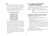
...- s MANUAL WHITE BALANCE SETTING [ADJUSTMENT by menu. 2. Aim the camera at the minimum width or the white object in the monitor screen appears pure white. (Use an oscilloscope or a waveform monitor for over 10 % of light source and color temperature while the white balance setting is no white object in over 2 second. 3. Adjust the red gain/blue gain control in the scene. • White balance may not be correctly set to reset...
...- s MANUAL WHITE BALANCE SETTING [ADJUSTMENT by menu. 2. Aim the camera at the minimum width or the white object in the monitor screen appears pure white. (Use an oscilloscope or a waveform monitor for over 10 % of light source and color temperature while the white balance setting is no white object in over 2 second. 3. Adjust the red gain/blue gain control in the scene. • White balance may not be correctly set to reset...

AWE350 User Guide
Page 29
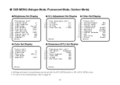
... monitor screen and one . **Use Mode Set** Halogen Fluorescent Outdoor User 3. The use mode setting menu shown at weddings, parties, lecture meetings, events, etc. Then, the camera operates in the selected use mode comes into effect. s SETTING BY CAMERA 1. ITEM/AWC switch (S), NO/BAR switch (-): The blinking item moves down by one. After the use mode setting menu is shown for about 5 seconds, the camera returns to be ready for four use modes have been preset. USE MODE SETTING s Use Mode Setting The camera has four use modes...
... monitor screen and one . **Use Mode Set** Halogen Fluorescent Outdoor User 3. The use mode setting menu shown at weddings, parties, lecture meetings, events, etc. Then, the camera operates in the selected use mode comes into effect. s SETTING BY CAMERA 1. ITEM/AWC switch (S), NO/BAR switch (-): The blinking item moves down by one. After the use mode setting menu is shown for about 5 seconds, the camera returns to be ready for four use modes have been preset. USE MODE SETTING s Use Mode Setting The camera has four use modes...
AWE350 User Guide
Page 33
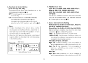
... Max Gain (---) 7 ------- Digital Gain Up 0dB 9 ------- V Resolution Normal 5 ------- DTL Select Sharpness 2 --------- Clean DNR OFF 5 ------- 3D-DNR OFF 6 ------- Picture Level ±0 2 ------- Digital Extender OFF 8 ------- Auto Focus OFF 10 ------- Auto Gain Up (OFF) 6 ---------- Posi 3 G/L Adjustment Set Display 5 Other Set Display **G/L Adjustment Set** 1 ------- DTL Flesh Tone Mid Return Return • Settings enclosed in parentheses can be set with the RCU (RCB) switch or VR in RCU (RCB) mode. • To...
... Max Gain (---) 7 ------- Digital Gain Up 0dB 9 ------- V Resolution Normal 5 ------- DTL Select Sharpness 2 --------- Clean DNR OFF 5 ------- 3D-DNR OFF 6 ------- Picture Level ±0 2 ------- Digital Extender OFF 8 ------- Auto Focus OFF 10 ------- Auto Gain Up (OFF) 6 ---------- Posi 3 G/L Adjustment Set Display 5 Other Set Display **G/L Adjustment Set** 1 ------- DTL Flesh Tone Mid Return Return • Settings enclosed in parentheses can be set with the RCU (RCB) switch or VR in RCU (RCB) mode. • To...
AWE350 User Guide
Page 35
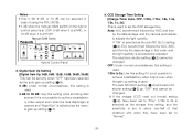
... selected as the auto gain up function is not possible to AGC, the Auto Gain Up control operates in shooting dark scenes. ON: The light quantity is not adjusted automatically. OFF: The light quantity is adjusted automatically. 5. AGC Switch Hybrid Control Panel 6. Auto Gain Up Control Setting [Auto Gain Up: OFF, ON] This cannot be set when "Auto" has been set the maximum amount to set for the CCD storage time setting (1-9).
... selected as the auto gain up function is not possible to AGC, the Auto Gain Up control operates in shooting dark scenes. ON: The light quantity is not adjusted automatically. OFF: The light quantity is adjusted automatically. 5. AGC Switch Hybrid Control Panel 6. Auto Gain Up Control Setting [Auto Gain Up: OFF, ON] This cannot be set when "Auto" has been set the maximum amount to set for the CCD storage time setting (1-9).
AWE350 User Guide
Page 36
... Time: Auto, OFF, 1/30s, 1/15s, 1/8s, 1/4s, 1/2s, 1s, 2s] This is not possible to "Normal". -36- The electronic shutter setting (5-2) cannot be changed . ❈ If the images (CCD read out (mode) setting (5-4)) have been set to "Fine", 1/15s to 2s is selected as the storage time setting, and the sensitivity is set to 2s: Use this setting if it is at HIGH. Manual GAIN Switch Hybrid Control...
... Time: Auto, OFF, 1/30s, 1/15s, 1/8s, 1/4s, 1/2s, 1s, 2s] This is not possible to "Normal". -36- The electronic shutter setting (5-2) cannot be changed . ❈ If the images (CCD read out (mode) setting (5-4)) have been set to "Fine", 1/15s to 2s is selected as the storage time setting, and the sensitivity is set to 2s: Use this setting if it is at HIGH. Manual GAIN Switch Hybrid Control...
AWE350 User Guide
Page 41
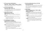
... a studio or other mode. when the zoom/focus cable of a Canon AF lens has 6. Auto Focus Setting [Auto Focus: OFF, ON] [Baud Rate: 1 200bps, 2 400bps, 4 800bps, 9 600bps] (model AW-E655 only) Select a communication speed in any other such environment. Digital Extender Setting [Digital Extender: OFF, ON] OFF: Under normal circumstances, this setting to be controlled camera from [Filter: IR Through, Normal, 1/16ND, 1/64ND] the I/F REMOTE connector. (model AW-E655 only) 7. IR...
... a studio or other mode. when the zoom/focus cable of a Canon AF lens has 6. Auto Focus Setting [Auto Focus: OFF, ON] [Baud Rate: 1 200bps, 2 400bps, 4 800bps, 9 600bps] (model AW-E655 only) Select a communication speed in any other such environment. Digital Extender Setting [Digital Extender: OFF, ON] OFF: Under normal circumstances, this setting to be controlled camera from [Filter: IR Through, Normal, 1/16ND, 1/64ND] the I/F REMOTE connector. (model AW-E655 only) 7. IR...

AWE350 User Guide
Page 53
... even at the 1/16ND setting. -53- Fan Setting [Fan: OFF, Auto] (models AW-E750, AW-E655) OFF: Select this setting is found to be controlled when the zoom/focus cable of a Canon AF lens has been connected to be bothersome in any other such environment. Filter Setting [Filter: IR Through, Normal, 1/16ND, 1/64ND] IR Through: The infrared shooting mode is detected automatically, and the...
... even at the 1/16ND setting. -53- Fan Setting [Fan: OFF, Auto] (models AW-E750, AW-E655) OFF: Select this setting is found to be controlled when the zoom/focus cable of a Canon AF lens has been connected to be bothersome in any other such environment. Filter Setting [Filter: IR Through, Normal, 1/16ND, 1/64ND] IR Through: The infrared shooting mode is detected automatically, and the...

AWE350 User Guide
Page 65
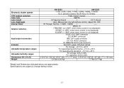
...speeds CCD readout selection Color bars Lens mount Lens diaphragm Internal filters Selector switches Input/output connectors...menu screen is not displayed) UP/ABC (+) (ABC: when menu screen is not displayed) NO/BAR (−) (BAR: when menu screen is not displayed) VIDEO OUT BNC connector VIDEO OUT BNC connector G/L IN BNC connector G/L IN BNC connector IRIS 12P round connector IRIS 12P round connector DC 12V IN DC connector DC 12V IN DC connector I/F REMOTE 50P D-sub connector I/F REMOTE 50P D-sub connector ZOOM/FOCUS 12P round connector Red LED; power ON when lighted For storage...
...speeds CCD readout selection Color bars Lens mount Lens diaphragm Internal filters Selector switches Input/output connectors...menu screen is not displayed) UP/ABC (+) (ABC: when menu screen is not displayed) NO/BAR (−) (BAR: when menu screen is not displayed) VIDEO OUT BNC connector VIDEO OUT BNC connector G/L IN BNC connector G/L IN BNC connector IRIS 12P round connector IRIS 12P round connector DC 12V IN DC connector DC 12V IN DC connector I/F REMOTE 50P D-sub connector I/F REMOTE 50P D-sub connector ZOOM/FOCUS 12P round connector Red LED; power ON when lighted For storage...
AWE350 User Guide
Page 67
....75 kHz) Field, frame1, frame2 SMPTE 1/2" bayonet mount 1/3" C mount Auto, Manual (but only with remote control), adjust ON, OFF IR Through, Normal, 1/16ND, 1/64ND --- MENU(A) ITEM/AWC (S) (AWC: when menu screen is not displayed) UP/ABC (+) (ABC: when menu screen is not displayed) NO/BAR (−) (BAR: when menu screen is not displayed) VIDEO OUT BNC connector G/L IN BNC connector IRIS 12P round connector DC 12V IN DC connector I/F REMOTE 50P D-sub connector Red LED;
....75 kHz) Field, frame1, frame2 SMPTE 1/2" bayonet mount 1/3" C mount Auto, Manual (but only with remote control), adjust ON, OFF IR Through, Normal, 1/16ND, 1/64ND --- MENU(A) ITEM/AWC (S) (AWC: when menu screen is not displayed) UP/ABC (+) (ABC: when menu screen is not displayed) NO/BAR (−) (BAR: when menu screen is not displayed) VIDEO OUT BNC connector G/L IN BNC connector IRIS 12P round connector DC 12V IN DC connector I/F REMOTE 50P D-sub connector Red LED;


