

AKHC931BP User Guide
Page 1
Multi-format camera AK-HC931BP Before attempting to connect, operate or adjust this product, please read these instructions completely.
Multi-format camera AK-HC931BP Before attempting to connect, operate or adjust this product, please read these instructions completely.
AKHC931BP User Guide
Page 4
... the lens ...11 Adjusting the lens flange back ...12 Performing the viewfinder adjustments ...13 Connecting the microphone ...15 Mounting the camera on a tripod ...16 Component system configuration ...17 System connections 1 (with multi-format camera 19 System connections 2 (with build-up unit) ...20 System connections 3 (with MSU) ...21 Status displays on viewfinder screen ...22 Menu...
... the lens ...11 Adjusting the lens flange back ...12 Performing the viewfinder adjustments ...13 Connecting the microphone ...15 Mounting the camera on a tripod ...16 Component system configuration ...17 System connections 1 (with multi-format camera 19 System connections 2 (with build-up unit) ...20 System connections 3 (with MSU) ...21 Status displays on viewfinder screen ...22 Menu...
AKHC931BP User Guide
Page 5
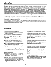
...accessory, can be further improved by combining Panasonic's unique horizontal line readout CCDs with a million pixels [1280 (H) 720 (V)]. Data trunk function Two RS-422 circuits are provided as the format, the VF signals are output in 1080I format Regardless of 74 MHz to ...ROP) and master setup unit (MSU). Using the ROP matrix, for the cables used to house the multi-format camera head to attain a high response and high resolution. Multi-functional enhancer In addition to the many functions such as the D/C output. The VF images ...
...accessory, can be further improved by combining Panasonic's unique horizontal line readout CCDs with a million pixels [1280 (H) 720 (V)]. Data trunk function Two RS-422 circuits are provided as the format, the VF signals are output in 1080I format Regardless of 74 MHz to ...ROP) and master setup unit (MSU). Using the ROP matrix, for the cables used to house the multi-format camera head to attain a high response and high resolution. Multi-functional enhancer In addition to the many functions such as the D/C output. The VF images ...
AKHC931BP User Guide
Page 8
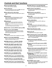
... also lights in such a way that the multi-format camera can be moved forward or backward once the two fixing screws are loosened. Optical fiber connector (EDW.3K made by LEMO) Camera power switch [POWER] This is used to select the camera power input (power supplied from the CCU or...to clamp the lens cable and mic cable in place. Tripod mount Before securing the multi-format camera to a tripod, attach the tripod adapter (SHAN-TM700) which is used to genlock the camera is input to select the genlock input or the input/output (genlock input and PROMPT output) signals...
... also lights in such a way that the multi-format camera can be moved forward or backward once the two fixing screws are loosened. Optical fiber connector (EDW.3K made by LEMO) Camera power switch [POWER] This is used to select the camera power input (power supplied from the CCU or...to clamp the lens cable and mic cable in place. Tripod mount Before securing the multi-format camera to a tripod, attach the tripod adapter (SHAN-TM700) which is used to genlock the camera is input to select the genlock input or the input/output (genlock input and PROMPT output) signals...
AKHC931BP User Guide
Page 9
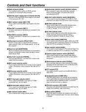
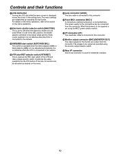
... knob This is used to select the video output (CAM, BAR or TEST). It is not effective when the CCU is connected to the camera. Camera output selector switch [OUTPUT] This is used to adjust the optical filter manually when LOCAL has been selected as return image selector switch. ... input gain selector switch This is used to set when there is inserted here. It is not effective when the CCU is connected to the camera. White balance selector switch [W.BAL] This is set the MIC2 input gain (in 10 dBm increments from this connector (open collector). Controls and...
... knob This is used to select the video output (CAM, BAR or TEST). It is not effective when the CCU is connected to the camera. Camera output selector switch [OUTPUT] This is used to adjust the optical filter manually when LOCAL has been selected as return image selector switch. ... input gain selector switch This is used to set when there is inserted here. It is not effective when the CCU is connected to the camera. White balance selector switch [W.BAL] This is set the MIC2 input gain (in 10 dBm increments from this connector (open collector). Controls and...
AKHC931BP User Guide
Page 10
... this connector. Front MIC1 connector [MIC1] A microphone (optional accessory) is connected here. It is not effective when the CCU is connected to the camera. VTR start/RET selector switch [VTR/RET] This is used . For details on the menu operations, refer to the section on the menu. ... Lens connector [LENS] The lens cable is to the camera. AWB/ABB start switch of the lens. When it is set using the monitor output selector switch. Rear VF connector This D-sub...
... this connector. Front MIC1 connector [MIC1] A microphone (optional accessory) is connected here. It is not effective when the CCU is connected to the camera. VTR start/RET selector switch [VTR/RET] This is used . For details on the menu operations, refer to the section on the menu. ... Lens connector [LENS] The lens cable is to the camera. AWB/ABB start switch of the lens. When it is set using the monitor output selector switch. Rear VF connector This D-sub...

AKHC931BP User Guide
Page 11
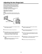
Flange back adjustment for the lens (performed using the controls on the camera) 3 Lower the lens clamp lever to clamp the lens in place. 11 Mount cap Lens clamp lever 2 Align the center mark on the lens mounted, ... lever, and remove the mount cap. 4 Insert the cable into the cable clamp and connect it may be necessary to perform the following lens and camera adjustments. 1. Auto iris operation speed adjustment for the lens 3.
Flange back adjustment for the lens (performed using the controls on the camera) 3 Lower the lens clamp lever to clamp the lens in place. 11 Mount cap Lens clamp lever 2 Align the center mark on the lens mounted, ... lever, and remove the mount cap. 4 Insert the cable into the cable clamp and connect it may be necessary to perform the following lens and camera adjustments. 1. Auto iris operation speed adjustment for the lens 3.
AKHC931BP User Guide
Page 12
... precisely focused at both the telephoto and wide-angle positions. 9 Tighten up the screw that secures the F.f ring. 12 Adjustment method For details on the camera. Adjusting the lens flange back Adjust the flange back (distance from the surface where the lens is obtained at both the telephoto and wide-angle...
... precisely focused at both the telephoto and wide-angle positions. 9 Tighten up the screw that secures the F.f ring. 12 Adjustment method For details on the camera. Adjusting the lens flange back Adjust the flange back (distance from the surface where the lens is obtained at both the telephoto and wide-angle...

AKHC931BP User Guide
Page 13
... OFF position. 2 Loosen the stopper screw, pull up the knob on the mounting plate and slide the plate to the viewfinder's connector, ensure that the camera's POWER switch is fully and securely inserted. Pull up the knob. 4 Tighten the stopper screw securely. Detaching the viewfinder 1 Check that it is at the...
... OFF position. 2 Loosen the stopper screw, pull up the knob on the mounting plate and slide the plate to the viewfinder's connector, ensure that the camera's POWER switch is fully and securely inserted. Pull up the knob. 4 Tighten the stopper screw securely. Detaching the viewfinder 1 Check that it is at the...
AKHC931BP User Guide
Page 15
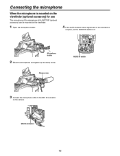
Microphone holder 2 Mount the microphone and tighten up the clamp screw. MIC IN connector 15 Clamp screw AUDIO IN switch 3 Connect the microphone cable to F. Connecting the microphone When the microphone is mounted on the viewfinder (optional accessory) for use The microphone of the microphone kit AJ-MC700P (optional accessory) can be mounted on the viewfinder. 1 Open the microphone holder. 4 If the audio channel whose signals are to be recorded so requires, set the AUDIO IN switch to the MIC IN connector on the camera.
Microphone holder 2 Mount the microphone and tighten up the clamp screw. MIC IN connector 15 Clamp screw AUDIO IN switch 3 Connect the microphone cable to F. Connecting the microphone When the microphone is mounted on the viewfinder (optional accessory) for use The microphone of the microphone kit AJ-MC700P (optional accessory) can be mounted on the viewfinder. 1 Open the microphone holder. 4 If the audio channel whose signals are to be recorded so requires, set the AUDIO IN switch to the MIC IN connector on the camera.

AKHC931BP User Guide
Page 16
... the red lever, move the black lever in the direction of the screws on the tripod platform. Slide the camera toward the back. Consider the center of gravity of the arrow, and slide the camera toward the front along the groove until a click is heard. 16 Bear in the direction of the... attachment Red lever Black lever If the pin of the tripod attachment fails to return to its original position after the camera has been detached, push the red lever again and simultaneously move the black lever in mind that the diameter of the selected holes match the ...
... the red lever, move the black lever in the direction of the screws on the tripod platform. Slide the camera toward the back. Consider the center of gravity of the arrow, and slide the camera toward the front along the groove until a click is heard. 16 Bear in the direction of the... attachment Red lever Black lever If the pin of the tripod attachment fails to return to its original position after the camera has been detached, push the red lever again and simultaneously move the black lever in mind that the diameter of the selected holes match the ...
AKHC931BP User Guide
Page 17
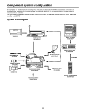
... to be controlled. The MSU (AK-MSU930P) is not required unless a multiple number of the multi-format camera (AK-HC931BP) and peripheral components is described below and shown on the following page. System block diagram Large lens Build-up unit AK-HBU931P ...Master setup unit AK-MSU930P Microphone kit AJ-MC700P 2 black-and-white viewfinder AJ-HVF20P Handy lens Multi-format camera AK-HC931BP Tripod attachment SHAN-TM700 8 LCD viewfinder AK-HVF931P Camera control unit AK-HCU931P ROP cable SD memory card RP-SD008B Remote operation panel AK-HRP931P 17 The basic ...
... to be controlled. The MSU (AK-MSU930P) is not required unless a multiple number of the multi-format camera (AK-HC931BP) and peripheral components is described below and shown on the following page. System block diagram Large lens Build-up unit AK-HBU931P ...Master setup unit AK-MSU930P Microphone kit AJ-MC700P 2 black-and-white viewfinder AJ-HVF20P Handy lens Multi-format camera AK-HC931BP Tripod attachment SHAN-TM700 8 LCD viewfinder AK-HVF931P Camera control unit AK-HCU931P ROP cable SD memory card RP-SD008B Remote operation panel AK-HRP931P 17 The basic ...
AKHC931BP User Guide
Page 18
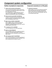
...is connected to 15 units either separately or simultaneously by remote control. Then turn on the multi-format camera. It is connected to the multi-format camera using the ROP cable (optional accessory), and enables the camera, CCU and lens to be operated when the system is built up to the CCU using... (the monitor system may be used , the MSU can be connected afterward), set the CCU's main power switch to 21 for the multi-format camera. As a standard feature, it supports SD video input and output, and it affords the same level of peripheral components Component connections in ...
...is connected to 15 units either separately or simultaneously by remote control. Then turn on the multi-format camera. It is connected to the multi-format camera using the ROP cable (optional accessory), and enables the camera, CCU and lens to be operated when the system is built up to the CCU using... (the monitor system may be used , the MSU can be connected afterward), set the CCU's main power switch to 21 for the multi-format camera. As a standard feature, it supports SD video input and output, and it affords the same level of peripheral components Component connections in ...

AKHC931BP User Guide
Page 19
System connections 1 (with multi-format camera) 2 viewfinder AJ-HVF20P Lens Multi-format camera AK-HC931BP Camera control unit AK-HCU931P ROP cable Remote operation panel AK-HRP931P Before proceeding with the connections, set the CCU power switch to the OFF position. Connect the multi-format camera to the CCU. ...Connect the ROP cable to the CCU and ROP. When the camera power switch is set to ON after the CCU main power switch has been set...
System connections 1 (with multi-format camera) 2 viewfinder AJ-HVF20P Lens Multi-format camera AK-HC931BP Camera control unit AK-HCU931P ROP cable Remote operation panel AK-HRP931P Before proceeding with the connections, set the CCU power switch to the OFF position. Connect the multi-format camera to the CCU. ...Connect the ROP cable to the CCU and ROP. When the camera power switch is set to ON after the CCU main power switch has been set...
AKHC931BP User Guide
Page 21
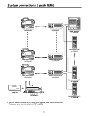
System connections 3 (with MSU) Multi-format camera AK-HC931BP Camera control unit 1 AK-HCU931P Master setup unit AK-MSU930P Multi-format camera AK-HC931BP Remote operation panel 1 AK-HRP931P Camera control unit 14 AK-HCU931P Multi-format camera AK-HC931BP Camera control unit 15 AK-HCU931P Remote operation panel 14 AK-HRP931P Large lens Build-up unit AK-HBU931P • A multiple number of cameras (up to 15 units) can be controlled in one location using the MSU. • The cameras can be controlled by both the ROPs and MSU. Remote operation panel 15 AK-HRP931P 21
System connections 3 (with MSU) Multi-format camera AK-HC931BP Camera control unit 1 AK-HCU931P Master setup unit AK-MSU930P Multi-format camera AK-HC931BP Remote operation panel 1 AK-HRP931P Camera control unit 14 AK-HCU931P Multi-format camera AK-HC931BP Camera control unit 15 AK-HCU931P Remote operation panel 14 AK-HRP931P Large lens Build-up unit AK-HBU931P • A multiple number of cameras (up to 15 units) can be controlled in one location using the MSU. • The cameras can be controlled by both the ROPs and MSU. Remote operation panel 15 AK-HRP931P 21
AKHC931BP User Guide
Page 22
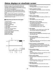
...display White balance memory display Gain display Audio CH1 and CH2 displays Iris f-number display Camera warning or message display Focus position display Zoom position display MONI SEL display Optical level display ... Audio CH1 and CH2 displays: The audio levels are also displayed. Status displays on viewfinder screen Besides the images, multi-format camera settings and messages indicating operating statuses appear on the viewfinder screen. P: The WHITE BAL switch is set to "B". A: The ...
...display White balance memory display Gain display Audio CH1 and CH2 displays Iris f-number display Camera warning or message display Focus position display Zoom position display MONI SEL display Optical level display ... Audio CH1 and CH2 displays: The audio levels are also displayed. Status displays on viewfinder screen Besides the images, multi-format camera settings and messages indicating operating statuses appear on the viewfinder screen. P: The WHITE BAL switch is set to "B". A: The ...
AKHC931BP User Guide
Page 23
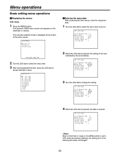
...item. 3 After having selected the item, press the JOG dial to access that item's menu. 2 When the JOG dial is entered. The camera's USER menu screen now appears on the viewfinder or monitor. Menu operations Basic setting menu operations Displaying the menus User menu 1 Press the... MENU button. The currently selected format is displayed at the bottom of the menu screen. Entering the menu data After accessing the item menus, enter the respective data. ...
...item. 3 After having selected the item, press the JOG dial to access that item's menu. 2 When the JOG dial is entered. The camera's USER menu screen now appears on the viewfinder or monitor. Menu operations Basic setting menu operations Displaying the menus User menu 1 Press the... MENU button. The currently selected format is displayed at the bottom of the menu screen. Entering the menu data After accessing the item menus, enter the respective data. ...

AKHC931BP User Guide
Page 28
... JOG dial. The images cannot be output properly if different video formats are used with the camera and the camera control unit. 3 Select "FORMAT SEL" and press the JOG dial. message is displayed, the video format selection will now be set to the video format which is not currently selected is displayed to the right of...
... JOG dial. The images cannot be output properly if different video formats are used with the camera and the camera control unit. 3 Select "FORMAT SEL" and press the JOG dial. message is displayed, the video format selection will now be set to the video format which is not currently selected is displayed to the right of...


