

AKHC931BP User Guide
Page 1
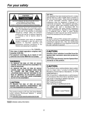
Multi-format camera AK-HC931BP Before attempting to connect, operate or adjust this product, please read these instructions completely.
Multi-format camera AK-HC931BP Before attempting to connect, operate or adjust this product, please read these instructions completely.
AKHC931BP User Guide
Page 2
... J. Warning: To assure continued FCC emission limit compliance, the user must use only shielded interface cables when connecting to qualified personnel. 2 Don't repair by yourself. NO USER SERVICEABLE PARTS INSIDE. Operation of the FCC Rules. For CANADA This class A digital apparatus complies with arrowhead symbol, within an equilateral triangle is operated in hazardous radiation exposure. CAUTION: TO REDUCE THE RISK OF...
... J. Warning: To assure continued FCC emission limit compliance, the user must use only shielded interface cables when connecting to qualified personnel. 2 Don't repair by yourself. NO USER SERVICEABLE PARTS INSIDE. Operation of the FCC Rules. For CANADA This class A digital apparatus complies with arrowhead symbol, within an equilateral triangle is operated in hazardous radiation exposure. CAUTION: TO REDUCE THE RISK OF...

AKHC931BP User Guide
Page 3
... the power cord form being walked on the unit and the applicable safety instructions listed below. A polarized plug has two blades with dry cloth. 7) Do not block any ventilation openings. When a cart is damaged, liquid has been spilled or objects have fallen into your safety. Keep these operating instructions handy for replacement of the obsolete outlet. 11) Only use attachments...
... the power cord form being walked on the unit and the applicable safety instructions listed below. A polarized plug has two blades with dry cloth. 7) Do not block any ventilation openings. When a cart is damaged, liquid has been spilled or objects have fallen into your safety. Keep these operating instructions handy for replacement of the obsolete outlet. 11) Only use attachments...
AKHC931BP User Guide
Page 4
... Performing the viewfinder adjustments ...13 Connecting the microphone ...15 Mounting the camera on a tripod ...16 Component system configuration ...17 System connections 1 (with multi-format camera 19 System connections 2 (with build-up unit) ...20 System connections 3 (with MSU) ...21 Status displays on viewfinder screen ...22 Menu operations ...23 Setting menu configuration ...25 How to select the video format ...28 AK-HC931BP connector pin assignment ...29 External dimension drawings ...30 Specifications ...31 4
... Performing the viewfinder adjustments ...13 Connecting the microphone ...15 Mounting the camera on a tripod ...16 Component system configuration ...17 System connections 1 (with multi-format camera 19 System connections 2 (with build-up unit) ...20 System connections 3 (with MSU) ...21 Status displays on viewfinder screen ...22 Menu operations ...23 Setting menu configuration ...25 How to select the video format ...28 AK-HC931BP connector pin assignment ...29 External dimension drawings ...30 Specifications ...31 4
AKHC931BP User Guide
Page 5
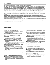
... designing the new circuitry to existing peripheral devices no need for the cables used with virtual control, pan/tilt head and lens control, etc. Features 720P and 1080I video formats supported Either the 720P or 1080I video format can be selected using the menu settings. The camera can be connected to consume less power and by combining the external shooting chart and internal test signals as well as the normal...
... designing the new circuitry to existing peripheral devices no need for the cables used with virtual control, pan/tilt head and lens control, etc. Features 720P and 1080I video formats supported Either the 720P or 1080I video format can be selected using the menu settings. The camera can be connected to consume less power and by combining the external shooting chart and internal test signals as well as the normal...
AKHC931BP User Guide
Page 8
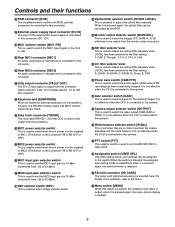
... the multi-format camera to a tripod, attach the tripod adapter (SHAN-TM700) which is used to genlock the camera is input to ON or OFF. Back tally LED This lights when the tally signal is supplied. RET switching control connector [RET CONT] The cable of the RET switching box (optional accessory) is connected here for controlling the ON/OFF settings of the PROMPT output...
... the multi-format camera to a tripod, attach the tripod adapter (SHAN-TM700) which is used to genlock the camera is input to ON or OFF. Back tally LED This lights when the tally signal is supplied. RET switching control connector [RET CONT] The cable of the RET switching box (optional accessory) is connected here for controlling the ON/OFF settings of the PROMPT output...
AKHC931BP User Guide
Page 9
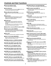
... is used to select the power supply status when VTR recording has been temporarily stopped. It is not effective when the CCU is connected to the camera. White balance selector switch [W.BAL] This is set when there is no time to select the video output (CAM, BAR or TEST). When the switch is pressed, the assigned user setting mode is established; when it is pressed again, the menu screen display...
... is used to select the power supply status when VTR recording has been temporarily stopped. It is not effective when the CCU is connected to the camera. White balance selector switch [W.BAL] This is set when there is no time to select the video output (CAM, BAR or TEST). When the switch is pressed, the assigned user setting mode is established; when it is pressed again, the menu screen display...
AKHC931BP User Guide
Page 10
... menu settings are established by operating this connector. Controls and their functions JOG dial button Turning the JOG dial while the menu screen is displayed moves the cursor to the SEL position, the shutter speed is switched in the preset range and the mode is also switched. It is not effective when the CCU is connected to the camera. AWB/ABB start switch [AUTO W/B BAL] This switch is operated...
... menu settings are established by operating this connector. Controls and their functions JOG dial button Turning the JOG dial while the menu screen is displayed moves the cursor to the SEL position, the shutter speed is switched in the preset range and the mode is also switched. It is not effective when the CCU is connected to the camera. AWB/ABB start switch [AUTO W/B BAL] This switch is operated...

AKHC931BP User Guide
Page 11
... lens, refer to the instructions that accompany the lens. Depending on the lens mounted, it to the LENS connector. Auto iris operation speed adjustment for the lens 2. White shading adjustment for the lens (performed using the controls on the lens with the groove at the top center of the lens mount, and mount the lens. Mounting the lens 1 Raise the lens clamp lever, and remove the mount cap. 4 Insert the cable...
... lens, refer to the instructions that accompany the lens. Depending on the lens mounted, it to the LENS connector. Auto iris operation speed adjustment for the lens 2. White shading adjustment for the lens (performed using the controls on the lens with the groove at the top center of the lens mount, and mount the lens. Mounting the lens 1 Raise the lens clamp lever, and remove the mount cap. 4 Insert the cable...
AKHC931BP User Guide
Page 12
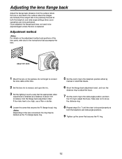
... either by manual or electrical means. 6 Shoot the flange back adjustment chart, and turn the distance ring to adjust the focus. 7 Set the zoom ring to the wide-angle position, and turn the F.f ring to the instructions that secures the F.f (flange focus) ring. Adjustment method For details on the camera. If the video level is too high, use a filter or shutter. 4 Loosen the screw that accompany the lens.
... either by manual or electrical means. 6 Shoot the flange back adjustment chart, and turn the distance ring to adjust the focus. 7 Set the zoom ring to the wide-angle position, and turn the F.f ring to the instructions that secures the F.f (flange focus) ring. Adjustment method For details on the camera. If the video level is too high, use a filter or shutter. 4 Loosen the screw that accompany the lens.

AKHC931BP User Guide
Page 13
... 3 Disconnect the plug from the viewfinder. 5 Connect the plug to the viewfinder's connector. When connecting the plug to the viewfinder's connector, ensure that it is fully and securely inserted. Detaching the viewfinder 1 Check that the camera's POWER switch is at the OFF position. 2 Attach the accessory mounting plate to the viewfinder. Remove mounting plate from the viewfinder cable connector. 13 Mounting...
... 3 Disconnect the plug from the viewfinder. 5 Connect the plug to the viewfinder's connector. When connecting the plug to the viewfinder's connector, ensure that it is fully and securely inserted. Detaching the viewfinder 1 Check that the camera's POWER switch is at the OFF position. 2 Attach the accessory mounting plate to the viewfinder. Remove mounting plate from the viewfinder cable connector. 13 Mounting...
AKHC931BP User Guide
Page 15
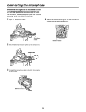
MIC IN connector 15 Clamp screw AUDIO IN switch 3 Connect the microphone cable to F. Microphone holder 2 Mount the microphone and tighten up the clamp screw. Connecting the microphone When the microphone is mounted on the viewfinder (optional accessory) for use The microphone of the microphone kit AJ-MC700P (optional accessory) can be mounted on the viewfinder. 1 Open the microphone holder. 4 If the audio channel whose signals are to be recorded so requires, set the AUDIO IN switch to the MIC IN connector on the camera.
MIC IN connector 15 Clamp screw AUDIO IN switch 3 Connect the microphone cable to F. Microphone holder 2 Mount the microphone and tighten up the clamp screw. Connecting the microphone When the microphone is mounted on the viewfinder (optional accessory) for use The microphone of the microphone kit AJ-MC700P (optional accessory) can be mounted on the viewfinder. 1 Open the microphone holder. 4 If the audio channel whose signals are to be recorded so requires, set the AUDIO IN switch to the MIC IN connector on the camera.
AKHC931BP User Guide
Page 17
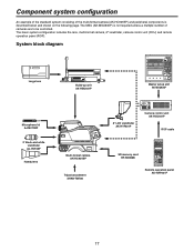
... configuration includes the lens, multi-format camera, 2 viewfinder, camera control unit (CCU) and remote operation panel (ROP). System block diagram Large lens Build-up unit AK-HBU931P Master setup unit AK-MSU930P Microphone kit AJ-MC700P 2 black-and-white viewfinder AJ-HVF20P Handy lens Multi-format camera AK-HC931BP Tripod attachment SHAN-TM700 8 LCD viewfinder AK-HVF931P Camera control unit AK-HCU931P ROP cable SD memory card RP-SD008B Remote operation panel AK...
... configuration includes the lens, multi-format camera, 2 viewfinder, camera control unit (CCU) and remote operation panel (ROP). System block diagram Large lens Build-up unit AK-HBU931P Master setup unit AK-MSU930P Microphone kit AJ-MC700P 2 black-and-white viewfinder AJ-HVF20P Handy lens Multi-format camera AK-HC931BP Tripod attachment SHAN-TM700 8 LCD viewfinder AK-HVF931P Camera control unit AK-HCU931P ROP cable SD memory card RP-SD008B Remote operation panel AK...
AKHC931BP User Guide
Page 18
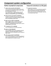
...;VF: AJ-HVF20P) This is the viewfinder for the component connections. It can be operated by remote control. 3 Master setup unit (MSU: AK-MSU930P) When a multiple number of cameras and CCUs are used, the MSU can also support HD video input and output by remote control. It can be connected afterward), set the CCU's main power switch to the ON position. Component system configuration Outline of peripheral components...
...;VF: AJ-HVF20P) This is the viewfinder for the component connections. It can be operated by remote control. 3 Master setup unit (MSU: AK-MSU930P) When a multiple number of cameras and CCUs are used, the MSU can also support HD video input and output by remote control. It can be connected afterward), set the CCU's main power switch to the ON position. Component system configuration Outline of peripheral components...

AKHC931BP User Guide
Page 19
... Lens Multi-format camera AK-HC931BP Camera control unit AK-HCU931P ROP cable Remote operation panel AK-HRP931P Before proceeding with the connections, set the CCU power switch to the OFF position. Connect the multi-format camera to the CCU. Connect the ROP cable to the CCU and ROP. When the camera power switch is set to ON after the CCU main power switch has been set to ON, the camera can be controlled using...
... Lens Multi-format camera AK-HC931BP Camera control unit AK-HCU931P ROP cable Remote operation panel AK-HRP931P Before proceeding with the connections, set the CCU power switch to the OFF position. Connect the multi-format camera to the CCU. Connect the ROP cable to the CCU and ROP. When the camera power switch is set to ON after the CCU main power switch has been set to ON, the camera can be controlled using...
AKHC931BP User Guide
Page 21
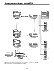
System connections 3 (with MSU) Multi-format camera AK-HC931BP Camera control unit 1 AK-HCU931P Master setup unit AK-MSU930P Multi-format camera AK-HC931BP Remote operation panel 1 AK-HRP931P Camera control unit 14 AK-HCU931P Multi-format camera AK-HC931BP Camera control unit 15 AK-HCU931P Remote operation panel 14 AK-HRP931P Large lens Build-up unit AK-HBU931P • A multiple number of cameras (up to 15 units) can be controlled in one location using the MSU. • The cameras can be controlled by both the ROPs and MSU. Remote operation panel 15 AK-HRP931P 21
System connections 3 (with MSU) Multi-format camera AK-HC931BP Camera control unit 1 AK-HCU931P Master setup unit AK-MSU930P Multi-format camera AK-HC931BP Remote operation panel 1 AK-HRP931P Camera control unit 14 AK-HCU931P Multi-format camera AK-HC931BP Camera control unit 15 AK-HCU931P Remote operation panel 14 AK-HRP931P Large lens Build-up unit AK-HBU931P • A multiple number of cameras (up to 15 units) can be controlled in one location using the MSU. • The cameras can be controlled by both the ROPs and MSU. Remote operation panel 15 AK-HRP931P 21
AKHC931BP User Guide
Page 22
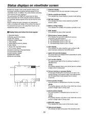
... the images, multi-format camera settings and messages indicating operating statuses appear on the viewfinder screen. B: The WHITE BAL switch is set to the viewfinder display appear at the top and bottom of filter selected. Extender display Shutter speed/mode display RET SEL display Battery voltage display Filter display White balance memory display Gain display Audio CH1 and CH2 displays Iris f-number display Camera warning or message display Focus position display Zoom position...
... the images, multi-format camera settings and messages indicating operating statuses appear on the viewfinder screen. B: The WHITE BAL switch is set to the viewfinder display appear at the top and bottom of filter selected. Extender display Shutter speed/mode display RET SEL display Battery voltage display Filter display White balance memory display Gain display Audio CH1 and CH2 displays Iris f-number display Camera warning or message display Focus position display Zoom position...
AKHC931BP User Guide
Page 23
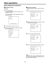
... menu item to be set to the flashing will remain unchanged. 23 The currently selected format is displayed at the bottom of the item indicated by the arrow flashes. 3 Turn the JOG dial to change the setting. 4 When the JOG dial is pressed, the data is flashing, the setting prior to OFF while the setting is entered. Menu operations Basic setting menu operations Displaying the menus User menu 1 Press the MENU button...
... menu item to be set to the flashing will remain unchanged. 23 The currently selected format is displayed at the bottom of the item indicated by the arrow flashes. 3 Turn the JOG dial to change the setting. 4 When the JOG dial is pressed, the data is flashing, the setting prior to OFF while the setting is entered. Menu operations Basic setting menu operations Displaying the menus User menu 1 Press the MENU button...

AKHC931BP User Guide
Page 28
... menu display ON/OFF operation is performed while the "TURN OFF POWER!" The arrow () now returns to the "FORMAT SEL" position.) 28 message is displayed, the video format selection will now be output properly if different video formats are used with the camera and the camera control unit. 3 Select "FORMAT SEL" and press the JOG dial. How to select the video format 1 From the Maintenance menu, select "VIDEO FORMAT". 2 The currently selected format...
... menu display ON/OFF operation is performed while the "TURN OFF POWER!" The arrow () now returns to the "FORMAT SEL" position.) 28 message is displayed, the video format selection will now be output properly if different video formats are used with the camera and the camera control unit. 3 Select "FORMAT SEL" and press the JOG dial. How to select the video format 1 From the Maintenance menu, select "VIDEO FORMAT". 2 The currently selected format...

AKHC931BP User Guide
Page 31
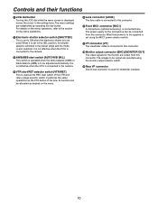
... been installed) Control 1) Power selection: EXT, OFF, CCU 2) USER SEL: Functions specified by menu items can be allocated to the switch. 3) RET A/B selection: For selecting the return signal 4) Front tally selection: Front tally HIGH, LOW, OFF (VF unit) 5) Viewfinder marker selection: Center marker, safety zone, 4:3 marker 6) Gain selection: LOW, MID, HIGH 7) Output selection: CAM, BAR, TEST 8) White balance mode: A, B, preset 9) Shutter speed selection...
... been installed) Control 1) Power selection: EXT, OFF, CCU 2) USER SEL: Functions specified by menu items can be allocated to the switch. 3) RET A/B selection: For selecting the return signal 4) Front tally selection: Front tally HIGH, LOW, OFF (VF unit) 5) Viewfinder marker selection: Center marker, safety zone, 4:3 marker 6) Gain selection: LOW, MID, HIGH 7) Output selection: CAM, BAR, TEST 8) White balance mode: A, B, preset 9) Shutter speed selection...


