
AKHC930 User Guide
Page 1
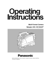
Multi-Format Camera Model AK-HC930P Before attempting to connect, operate or adjust this product, please read these instructions completely.
Multi-Format Camera Model AK-HC930P Before attempting to connect, operate or adjust this product, please read these instructions completely.
AKHC930 User Guide
Page 3
Contents For your safety 2 Overview 4 Features 4 Controls and their functions 5 Mounting the lens 10 Adjusting the lens flange back 11 Performing the viewfinder adjustments 12 Connecting the microphone 14 Mounting the camera on a tripod 15 Component system configuration 16 System connections 1 (with Multi-Format Camera 18 System connections 2 (with build-up unit 19 System connections 3 (with MSU 20 Status displays on viewfinder screen 21 Menu operations 22 Setting menu configuration 24 AK-HC930P Connector pin assignment 27 External dimension drawings 28 Specifications 29 3
Contents For your safety 2 Overview 4 Features 4 Controls and their functions 5 Mounting the lens 10 Adjusting the lens flange back 11 Performing the viewfinder adjustments 12 Connecting the microphone 14 Mounting the camera on a tripod 15 Component system configuration 16 System connections 1 (with Multi-Format Camera 18 System connections 2 (with build-up unit 19 System connections 3 (with MSU 20 Status displays on viewfinder screen 21 Menu operations 22 Setting menu configuration 24 AK-HC930P Connector pin assignment 27 External dimension drawings 28 Specifications 29 3
AKHC930 User Guide
Page 4
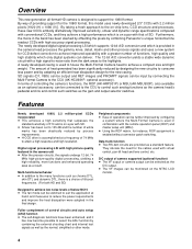
... Newly developed 1080I, 2.2 million-pixel CCDs incorporated ≥ This achieves a high sensitivity that of providing support for the cables used to house the Multi-Format Camera head to the CCU (AK-HCU931P, optional accessory). Peripheral components ≥ Ease of 74 MHz to reduce the power requirements and improve the heat dissipation...with a high signal-to-noise ratio from the dark areas to suit the application at a frequency of operation can be further improved by combining Panasonic's unique horizontal line readout CCDs with 2.2 million pixels [1920 (H) x 1080 (V)].
... Newly developed 1080I, 2.2 million-pixel CCDs incorporated ≥ This achieves a high sensitivity that of providing support for the cables used to house the Multi-Format Camera head to the CCU (AK-HCU931P, optional accessory). Peripheral components ≥ Ease of 74 MHz to reduce the power requirements and improve the heat dissipation...with a high signal-to-noise ratio from the dark areas to suit the application at a frequency of operation can be further improved by combining Panasonic's unique horizontal line readout CCDs with 2.2 million pixels [1920 (H) x 1080 (V)].
AKHC930 User Guide
Page 6
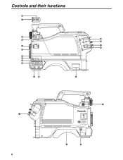
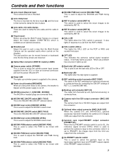
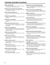
Controls and their functions V _ PTT RET W X Y Z ^ ] \ [ NAM R G Y /C B FILTER LOCAL MONI SEL 1A ND FILTER CC 1 CAP 3200K A 2 CLEAR 4300K B 3 1 / 4ND 6300K C 4 1/16ND CROSS D 5 1/64ND DF0 E CAM/VTR GAIN ON ON LOW OUTPUT CAM W.BAL B MID BAR A STBY SAVE HIGH TEST PRST PTT USER SEL _` PHANT OFF PHANT OFF AB AB -40 -30 -20 -40 -30 -50 -60 -20 -50 -60 (dB) (dB) MIC1 MIC2 R S U T a F OPT FIBER HD SDI OUT AUX OUT PROMPTER/GL 6 VF E 1 ULTI FORMAT DIGITAL CAMERA SYSTEM MONITOR OUT LENS MIC1 j i
Controls and their functions V _ PTT RET W X Y Z ^ ] \ [ NAM R G Y /C B FILTER LOCAL MONI SEL 1A ND FILTER CC 1 CAP 3200K A 2 CLEAR 4300K B 3 1 / 4ND 6300K C 4 1/16ND CROSS D 5 1/64ND DF0 E CAM/VTR GAIN ON ON LOW OUTPUT CAM W.BAL B MID BAR A STBY SAVE HIGH TEST PRST PTT USER SEL _` PHANT OFF PHANT OFF AB AB -40 -30 -20 -40 -30 -50 -60 -20 -50 -60 (dB) (dB) MIC1 MIC2 R S U T a F OPT FIBER HD SDI OUT AUX OUT PROMPTER/GL 6 VF E 1 ULTI FORMAT DIGITAL CAMERA SYSTEM MONITOR OUT LENS MIC1 j i
AKHC930 User Guide
Page 7
...selector switch is set the back tally LED to be mixed with INCOM2. A OPT LED This indicates the camera's optical signal reception status. When any problem has occurred, it is connected here for controlling the ON/OFF ... ON or OFF. D Tripod mount Before securing the Multi-Format Camera to a tripod, attach the tripod adapter (SHAN-TM700) which is used to genlock the camera is mounted. The pad position can be moved forward or backward... the PGM to clamp the lens in such a way that the Multi-Format Camera can be operated easily when carried on the ROP or MSU and sounds the buzzer.
...selector switch is set the back tally LED to be mixed with INCOM2. A OPT LED This indicates the camera's optical signal reception status. When any problem has occurred, it is connected here for controlling the ON/OFF ... ON or OFF. D Tripod mount Before securing the Multi-Format Camera to a tripod, attach the tripod adapter (SHAN-TM700) which is used to genlock the camera is mounted. The pad position can be moved forward or backward... the PGM to clamp the lens in such a way that the Multi-Format Camera can be operated easily when carried on the ROP or MSU and sounds the buzzer.
AKHC930 User Guide
Page 8
... settings can be supplied to MIC2. (The switch is set when there is released. It is not effective when the CCU is connected to the camera. _ PTT switch [PTT] This selector switch is connected to this switch. R MIC1 power selector switch This is used to select what kind of... this jack, the INCOM1 receive signal and MIC1 monitor signal can also supplied. For details on its operation, refer to select the gain for the camera images. Controls and their functions J RCB connector [RCB] The simplified remote control unit (RCB, optional accessory) is used to select the video output (...
... settings can be supplied to MIC2. (The switch is set when there is released. It is not effective when the CCU is connected to the camera. _ PTT switch [PTT] This selector switch is connected to this switch. R MIC1 power selector switch This is used to select what kind of... this jack, the INCOM1 receive signal and MIC1 monitor signal can also supplied. For details on its operation, refer to select the gain for the camera images. Controls and their functions J RCB connector [RCB] The simplified remote control unit (RCB, optional accessory) is used to select the video output (...

AKHC930 User Guide
Page 9
For details on the menu operations, refer to the camera. It performs the same operations as desired on the menu operations. The images to be adjusted automatically. Controls and their functions c JOG dial button Turning ... used as the REC start switch [AUTO W/B BAL] This switch is operated when the white balance (AWB) or black balance (ABB) is set to the camera. When it is to be allocated as the VTR button of the VTR and return image selector switch. d Electronic shutter selector switch [SHUTTER] This is...
For details on the menu operations, refer to the camera. It performs the same operations as desired on the menu operations. The images to be adjusted automatically. Controls and their functions c JOG dial button Turning ... used as the REC start switch [AUTO W/B BAL] This switch is operated when the white balance (AWB) or black balance (ABB) is set to the camera. When it is to be allocated as the VTR button of the VTR and return image selector switch. d Electronic shutter selector switch [SHUTTER] This is...

AKHC930 User Guide
Page 10
Center mark ≥ For details on handling the lens, refer to the instructions that accompany the lens. ≥ Depending on the camera) 3 Lower the lens clamp lever to clamp the lens in place. 10 Flange back adjustment for the lens 3. Mounting the lens 1 Raise the ... to the LENS connector. White shading adjustment for the lens (performed using the controls on the lens mounted, it to perform the following lens and camera adjustments. 1. Auto iris operation speed adjustment for the lens 2. Mount cap Lens clamp lever LENS connector 2 Align the center mark on the lens ...
Center mark ≥ For details on handling the lens, refer to the instructions that accompany the lens. ≥ Depending on the camera) 3 Lower the lens clamp lever to clamp the lens in place. 10 Flange back adjustment for the lens 3. Mounting the lens 1 Raise the ... to the LENS connector. White shading adjustment for the lens (performed using the controls on the lens mounted, it to perform the following lens and camera adjustments. 1. Auto iris operation speed adjustment for the lens 2. Mount cap Lens clamp lever LENS connector 2 Align the center mark on the lens ...
AKHC930 User Guide
Page 11
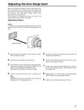
... are to be precisely focused at both the telephoto and wide-angle positions. 9 Tighten up the screw that secures the F.f ring. 11 Depending on the camera. Adjusting the lens flange back Adjust the flange back (distance from the flange back adjustment chart. Once adjusted, the flange back does not need to...
... are to be precisely focused at both the telephoto and wide-angle positions. 9 Tighten up the screw that secures the F.f ring. 11 Depending on the camera. Adjusting the lens flange back Adjust the flange back (distance from the flange back adjustment chart. Once adjusted, the flange back does not need to...

AKHC930 User Guide
Page 12
...on the mounting plate and slide the viewfinder along and off the plate. When connecting the plug to the viewfinder's connector, ensure that the camera's POWER switch is at the OFF position. 2 Attach the accessory mounting plate to the viewfinder. 5 Connect the plug to the viewfinder's ...plate from the viewfinder cable connector. 12 Performing the viewfinder adjustments (The viewfinder is an optional accessory.) Attaching the viewfinder 1 Check that the camera's POWER switch is at the OFF position. 2 Loosen the stopper screw, pull up the knob on the mounting plate and slide the plate...
...on the mounting plate and slide the viewfinder along and off the plate. When connecting the plug to the viewfinder's connector, ensure that the camera's POWER switch is at the OFF position. 2 Attach the accessory mounting plate to the viewfinder. 5 Connect the plug to the viewfinder's ...plate from the viewfinder cable connector. 12 Performing the viewfinder adjustments (The viewfinder is an optional accessory.) Attaching the viewfinder 1 Check that the camera's POWER switch is at the OFF position. 2 Loosen the stopper screw, pull up the knob on the mounting plate and slide the plate...
AKHC930 User Guide
Page 14
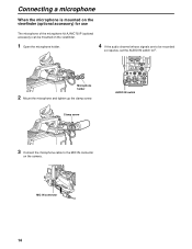
... holder. 4 If the audio channel whose signals are to be recorded so requires, set the AUDIO IN switch to the MIC IN connector on the camera. MIC IN connector 14 Microphone holder 2 Mount the microphone and tighten up the clamp screw.
... holder. 4 If the audio channel whose signals are to be recorded so requires, set the AUDIO IN switch to the MIC IN connector on the camera. MIC IN connector 14 Microphone holder 2 Mount the microphone and tighten up the clamp screw.

AKHC930 User Guide
Page 15
...) MIC1 MIC2 15 Tripod attachment Red lever Black lever If the pin of the tripod attachment fails to return to its original position after the camera has been detached, push the red lever again and simultaneously move the black lever in the direction of the arrow, and slide the... camera toward the front along the groove until a click is heard. Slide the camera toward the back. Bear in mind that the diameter of the selected holes match the diameter of the...
...) MIC1 MIC2 15 Tripod attachment Red lever Black lever If the pin of the tripod attachment fails to return to its original position after the camera has been detached, push the red lever again and simultaneously move the black lever in the direction of the arrow, and slide the... camera toward the front along the groove until a click is heard. Slide the camera toward the back. Bear in mind that the diameter of the selected holes match the diameter of the...
AKHC930 User Guide
Page 16
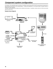
... CHARACTER RST ALARM OPT FAN CABLE 60Hz MODE FLARE BLK GAMMA AUTO KNEE WHITE MATRIX HD. The basic system configuration includes the lens, Multi-Format Camera, 2z viewfinder, camera control unit (CCU) and remote operation panel (ROP). FACE SD. DTL SD. CLIP KNEE HD. DTL HD.FACE SD. DTL SD. ...dB) (dB) MIC1 MIC2 CAM/VTR GAIN ON ON LOW OUTPUT CAM W.BAL B MID BAR A STBY SAVE HIGH TEST PRST PTT USER SEL Multi-Format Camera AK-HC930P Tripod attachment SHAN-TM700 8z LCD viewfinder AK-HVF931P CABLE OPEN SHORT ALARM FUSE 125V 5A FUSE 250V 2.5A TALLY/CALL MAIN HEAD...
... CHARACTER RST ALARM OPT FAN CABLE 60Hz MODE FLARE BLK GAMMA AUTO KNEE WHITE MATRIX HD. The basic system configuration includes the lens, Multi-Format Camera, 2z viewfinder, camera control unit (CCU) and remote operation panel (ROP). FACE SD. DTL SD. CLIP KNEE HD. DTL HD.FACE SD. DTL SD. ...dB) (dB) MIC1 MIC2 CAM/VTR GAIN ON ON LOW OUTPUT CAM W.BAL B MID BAR A STBY SAVE HIGH TEST PRST PTT USER SEL Multi-Format Camera AK-HC930P Tripod attachment SHAN-TM700 8z LCD viewfinder AK-HVF931P CABLE OPEN SHORT ALARM FUSE 125V 5A FUSE 250V 2.5A TALLY/CALL MAIN HEAD...
AKHC930 User Guide
Page 17
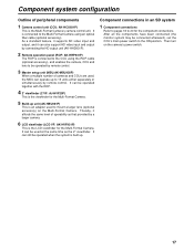
...of operability as the 2z viewfinder. It can still be operated when the system is connected to the Multi-Format Camera using the ROP cable (optional accessory), and enables the camera, CCU and lens to be operated together with the ROP. 4 2z viewfinder (2zVF: AJ-HVF20P) ...This is an adapter used to mount a larger lens (optional accessory) on the camera's power switch. 17 Then turn on the Multi-Format Camera. It can operate up unit (AK-HBU931P) This is the Multi-Format Camera's camera control unit. Component connections in an SD system 1 Component connections Refer to pages...
...of operability as the 2z viewfinder. It can still be operated when the system is connected to the Multi-Format Camera using the ROP cable (optional accessory), and enables the camera, CCU and lens to be operated together with the ROP. 4 2z viewfinder (2zVF: AJ-HVF20P) ...This is an adapter used to mount a larger lens (optional accessory) on the camera's power switch. 17 Then turn on the Multi-Format Camera. It can operate up unit (AK-HBU931P) This is the Multi-Format Camera's camera control unit. Component connections in an SD system 1 Component connections Refer to pages...
AKHC930 User Guide
Page 18
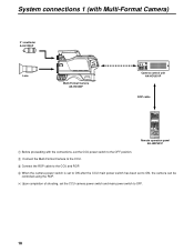
... M-PEDACTIVE LENS EXT X0.8 CALL PED SENSE IRIS PED IRIS RANGE Remote Operation Panel AK-HRP930P Remote operation panel AK-HRP931P 1 Before proceeding with Multi-Format Camera) 2z viewfinder AJ-HVF20P Lens NAM R G Y /C B FILTER LOCAL MONI SEL 1A ND FILTER CC 1 CAP 3200K A 2 CLEAR 4300K B 3 1 / 4ND 6300K C 4 1/...MIC2 CAM/VTR GAIN ON ON LOW OUTPUT CAM W.BAL B MID BAR A STBY SAVE HIGH TEST PRST PTT USER SEL Multi-Format Camera AK-HC930P CABLE OPEN SHORT ALARM FUSE 125V 5A FUSE 250V 2.5A TALLY/CALL MAIN HEAD POWER LEVEL COXN PGN1 PGN OFF PGN2 ...
... M-PEDACTIVE LENS EXT X0.8 CALL PED SENSE IRIS PED IRIS RANGE Remote Operation Panel AK-HRP930P Remote operation panel AK-HRP931P 1 Before proceeding with Multi-Format Camera) 2z viewfinder AJ-HVF20P Lens NAM R G Y /C B FILTER LOCAL MONI SEL 1A ND FILTER CC 1 CAP 3200K A 2 CLEAR 4300K B 3 1 / 4ND 6300K C 4 1/...MIC2 CAM/VTR GAIN ON ON LOW OUTPUT CAM W.BAL B MID BAR A STBY SAVE HIGH TEST PRST PTT USER SEL Multi-Format Camera AK-HC930P CABLE OPEN SHORT ALARM FUSE 125V 5A FUSE 250V 2.5A TALLY/CALL MAIN HEAD POWER LEVEL COXN PGN1 PGN OFF PGN2 ...
AKHC930 User Guide
Page 19
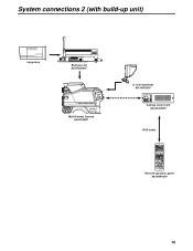
... MIC1 MIC2 CAM/VTR GAIN ON ON LOW OUTPUT CAM W.BAL B MID BAR A STBY SAVE HIGH TEST PRST PTT USER SEL Multi-Format Camera AK-HC930P 8z LCD viewfinder AK-HVF931P CABLE OPEN SHORT ALARM FUSE 125V 5A FUSE 250V 2.5A TALLY/CALL MAIN HEAD POWER LEVEL COXN ...PGN1 PGN OFF PGN2 PUSH PRIVATE MIC ON OFF PTT Camera control unit AK-HCU931P ROP cable ROP ON HEAD ON VFPW CAMERA NO. DTL MATRIX SYSTEM FUNC FILTER ND HEAD CAP 100 25 6.3 1.6 1 SCENE FILE 2 3 4 5 STORE R 1 2 3 4 5 R GAIN G B CC 1.1 4.3 ...
... MIC1 MIC2 CAM/VTR GAIN ON ON LOW OUTPUT CAM W.BAL B MID BAR A STBY SAVE HIGH TEST PRST PTT USER SEL Multi-Format Camera AK-HC930P 8z LCD viewfinder AK-HVF931P CABLE OPEN SHORT ALARM FUSE 125V 5A FUSE 250V 2.5A TALLY/CALL MAIN HEAD POWER LEVEL COXN ...PGN1 PGN OFF PGN2 PUSH PRIVATE MIC ON OFF PTT Camera control unit AK-HCU931P ROP cable ROP ON HEAD ON VFPW CAMERA NO. DTL MATRIX SYSTEM FUNC FILTER ND HEAD CAP 100 25 6.3 1.6 1 SCENE FILE 2 3 4 5 STORE R 1 2 3 4 5 R GAIN G B CC 1.1 4.3 ...
AKHC930 User Guide
Page 20
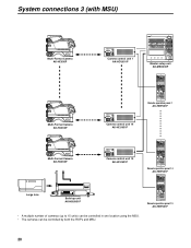
... (dB) MIC1 MIC2 CAM/VTR GAIN ON ON LOW OUTPUT CAM W.BAL B MID BAR A STBY SAVE HIGH TEST PRST PTT USER SEL Multi-Format Camera AK-HC930P CABLE OPEN SHORT ALARM FUSE 125V 5A FUSE 250V 2.5A TALLY/CALL MAIN HEAD POWER LEVEL COXN PGN1 PGN OFF PGN2 PUSH PRIVATE... -60 (dB) (dB) MIC1 MIC2 CAM/VTR GAIN ON ON LOW OUTPUT CAM W.BAL B MID BAR A STBY SAVE HIGH TEST PRST PTT USER SEL Multi-Format Camera AK-HC930P R NAM G Y /C B FILTER LOCAL MONI SEL 1A ND FILTER CC 1 CAP 3200K A 2 CLEAR 4300K B 3 1 / 4ND 6300K C 4 1/16ND CROSS D 5 1/64ND DF0 E ...
... (dB) MIC1 MIC2 CAM/VTR GAIN ON ON LOW OUTPUT CAM W.BAL B MID BAR A STBY SAVE HIGH TEST PRST PTT USER SEL Multi-Format Camera AK-HC930P CABLE OPEN SHORT ALARM FUSE 125V 5A FUSE 250V 2.5A TALLY/CALL MAIN HEAD POWER LEVEL COXN PGN1 PGN OFF PGN2 PUSH PRIVATE... -60 (dB) (dB) MIC1 MIC2 CAM/VTR GAIN ON ON LOW OUTPUT CAM W.BAL B MID BAR A STBY SAVE HIGH TEST PRST PTT USER SEL Multi-Format Camera AK-HC930P R NAM G Y /C B FILTER LOCAL MONI SEL 1A ND FILTER CC 1 CAP 3200K A 2 CLEAR 4300K B 3 1 / 4ND 6300K C 4 1/16ND CROSS D 5 1/64ND DF0 E ...
AKHC930 User Guide
Page 21
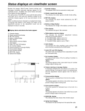
... also displayed. F14 Z99 56 7 88 3 9 < 1 Extender display: This appears when the lens extender is being used . : Camera warning or message display: A message indicating the occurrence of filter selected. 6 White balance memory display: This indicates the automatic adjustment selected for... . < Zoom position display: The zoom position is set to "PRST." Status displays on viewfinder screen Besides the images, Multi-Format Camera settings and messages indicating operating statuses appear on the viewfinder screen. Focus position display < Zoom position display = MONI SEL display >...
... also displayed. F14 Z99 56 7 88 3 9 < 1 Extender display: This appears when the lens extender is being used . : Camera warning or message display: A message indicating the occurrence of filter selected. 6 White balance memory display: This indicates the automatic adjustment selected for... . < Zoom position display: The zoom position is set to "PRST." Status displays on viewfinder screen Besides the images, Multi-Format Camera settings and messages indicating operating statuses appear on the viewfinder screen. Focus position display < Zoom position display = MONI SEL display >...

AKHC930 User Guide
Page 22
... remain unchanged. 22 Operation VF Setting1 VF Setting2 VF Display1 VF Display2 Setting1 Setting2 Setting3 INCOM !LED 7"VF 2 When the JOG dial is entered. The camera's USER menu screen now appears on the viewfinder or monitor. VF Setting1 Side Modulation 15 Zone Mark 4:3 Safety Mark 16:9 Center Mark OFF Center Mark...
... remain unchanged. 22 Operation VF Setting1 VF Setting2 VF Display1 VF Display2 Setting1 Setting2 Setting3 INCOM !LED 7"VF 2 When the JOG dial is entered. The camera's USER menu screen now appears on the viewfinder or monitor. VF Setting1 Side Modulation 15 Zone Mark 4:3 Safety Mark 16:9 Center Mark OFF Center Mark...

AKHC930 User Guide
Page 24
... Viewfinder settings1 VF Setting2 Viewfinder settings2 VF Display1 Viewfinder display settings VF Display2 Viewfinder display settings Setting1 Camera settings1 Setting2 Camera settings2 Setting3 Camera settings3 INCOM INCOM settings !LED Camera status display settings 24 7"VF Side Modulation (for changing the brightness level of the signals outside the... the gain SW to MID gain) GAIN SW HIGH (for setting the gain SW to HIGH gain) ID NUMBER (for setting the camera number and designation) CH1 ENG/PD (for switching INCOM1) CH2 ENG/PD (for switching INCOM2) CH1 CCU/CRANE (for switching crane...
... Viewfinder settings1 VF Setting2 Viewfinder settings2 VF Display1 Viewfinder display settings VF Display2 Viewfinder display settings Setting1 Camera settings1 Setting2 Camera settings2 Setting3 Camera settings3 INCOM INCOM settings !LED Camera status display settings 24 7"VF Side Modulation (for changing the brightness level of the signals outside the... the gain SW to MID gain) GAIN SW HIGH (for setting the gain SW to HIGH gain) ID NUMBER (for setting the camera number and designation) CH1 ENG/PD (for switching INCOM1) CH2 ENG/PD (for switching INCOM2) CH1 CCU/CRANE (for switching crane...


