
AKHC930 User Guide
Page 1
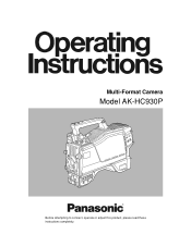
Multi-Format Camera Model AK-HC930P Before attempting to connect, operate or adjust this product, please read these instructions completely.
Multi-Format Camera Model AK-HC930P Before attempting to connect, operate or adjust this product, please read these instructions completely.

AKHC930 User Guide
Page 2
... may result in the literature accompanying the appliance. Don't repair by yourself. indicates safety information. 2 NO USER SERVICEABLE PARTS INSIDE. The lightning flash with Canadian ICES-003. CAUTION: This product uses a semiconductor laser system and is turned on. REFER TO SERVICING TO QUALIFIED SERVICE PERSONNEL. To assure continued compliance follow the attached installation instructions and do not make any unauthorized modifications...
... may result in the literature accompanying the appliance. Don't repair by yourself. indicates safety information. 2 NO USER SERVICEABLE PARTS INSIDE. The lightning flash with Canadian ICES-003. CAUTION: This product uses a semiconductor laser system and is turned on. REFER TO SERVICING TO QUALIFIED SERVICE PERSONNEL. To assure continued compliance follow the attached installation instructions and do not make any unauthorized modifications...
AKHC930 User Guide
Page 3
Contents For your safety 2 Overview 4 Features 4 Controls and their functions 5 Mounting the lens 10 Adjusting the lens flange back 11 Performing the viewfinder adjustments 12 Connecting the microphone 14 Mounting the camera on a tripod 15 Component system configuration 16 System connections 1 (with Multi-Format Camera 18 System connections 2 (with build-up unit 19 System connections 3 (with MSU 20 Status displays on viewfinder screen 21 Menu operations 22 Setting menu configuration 24 AK-HC930P Connector pin assignment 27 External dimension drawings 28 Specifications 29 3
Contents For your safety 2 Overview 4 Features 4 Controls and their functions 5 Mounting the lens 10 Adjusting the lens flange back 11 Performing the viewfinder adjustments 12 Connecting the microphone 14 Mounting the camera on a tripod 15 Component system configuration 16 System connections 1 (with Multi-Format Camera 18 System connections 2 (with build-up unit 19 System connections 3 (with MSU 20 Status displays on viewfinder screen 21 Menu operations 22 Setting menu configuration 24 AK-HC930P Connector pin assignment 27 External dimension drawings 28 Specifications 29 3
AKHC930 User Guide
Page 4
... where the Multi-Format Camera is provided in combination with the remote operation panel (ROP) and master setup unit (MSU). ≥ Using the ROP matrix, for the 1080I format, this model uses newly developed 2/3z CCDs with virtual control, pan-tilt head and lens control, etc. D/C output of 74 MHz to 135 dB and the number of white marks has been drastically reduced by combining Panasonic's unique horizontal...
... where the Multi-Format Camera is provided in combination with the remote operation panel (ROP) and master setup unit (MSU). ≥ Using the ROP matrix, for the 1080I format, this model uses newly developed 2/3z CCDs with virtual control, pan-tilt head and lens control, etc. D/C output of 74 MHz to 135 dB and the number of white marks has been drastically reduced by combining Panasonic's unique horizontal...
AKHC930 User Guide
Page 7
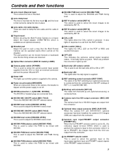
... been installed, the camera's D/C images (VBS) are connected here. C Lens cable, mic cable clamps These are output from an external connector) and turn the power ON and OFF. 2 Power LED This lights up green. CALL LED This lights when the CALL switch is used to select the PGM to clamp the lens in such a way that the Multi-Format Camera can be mixed with INCOM2. E Shoulder pad Adjust this connector. B Lens clamp...
... been installed, the camera's D/C images (VBS) are connected here. C Lens cable, mic cable clamps These are output from an external connector) and turn the power ON and OFF. 2 Power LED This lights up green. CALL LED This lights when the CALL switch is used to select the PGM to clamp the lens in such a way that the Multi-Format Camera can be mixed with INCOM2. E Shoulder pad Adjust this connector. B Lens clamp...
AKHC930 User Guide
Page 8
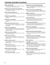
... the CCU is connected to the camera. ] Camera output selector switch [OUTPUT] This is connected to this connector (open collector). M Rear MIC1 connector [MIC1] An audio component or microphone is used to select the video output (CAM, BAR or TEST). U MIC2 input gain selector switch This is used to set the INCOM1 MIC to ON or OFF. ` Assignable switch [USER SEL] Using the setting menu, user settings can be heard. For details on its operation, refer to...
... the CCU is connected to the camera. ] Camera output selector switch [OUTPUT] This is connected to this connector (open collector). M Rear MIC1 connector [MIC1] An audio component or microphone is used to select the video output (CAM, BAR or TEST). U MIC2 input gain selector switch This is used to set the INCOM1 MIC to ON or OFF. ` Assignable switch [USER SEL] Using the setting menu, user settings can be heard. For details on its operation, refer to...

AKHC930 User Guide
Page 9
... connected to the setting items. The menu settings are selected using the MIC1 power selector switch. Controls and their functions c JOG dial button Turning the JOG dial while the menu screen is displayed moves the cursor to the camera. d Electronic shutter selector switch [SHUTTER] This is set to be supplied is also switched. h Front MIC1 connector [MIC1] A microphone (optional accessory) is to this dial button. The images to the SEL position, the shutter speed is switched...
... connected to the setting items. The menu settings are selected using the MIC1 power selector switch. Controls and their functions c JOG dial button Turning the JOG dial while the menu screen is displayed moves the cursor to the camera. d Electronic shutter selector switch [SHUTTER] This is set to be supplied is also switched. h Front MIC1 connector [MIC1] A microphone (optional accessory) is to this dial button. The images to the SEL position, the shutter speed is switched...

AKHC930 User Guide
Page 10
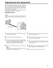
Auto iris operation speed adjustment for the lens 2. Center mark ≥ For details on handling the lens, refer to the instructions that accompany the lens. ≥ Depending on the lens mounted, it to the LENS connector. Flange back adjustment for the lens 3. White shading adjustment for the lens (performed using the controls on the lens with the groove at the top center of the lens mount, and mount the lens. Mount...
Auto iris operation speed adjustment for the lens 2. Center mark ≥ For details on handling the lens, refer to the instructions that accompany the lens. ≥ Depending on the lens mounted, it to the LENS connector. Flange back adjustment for the lens 3. White shading adjustment for the lens (performed using the controls on the lens with the groove at the top center of the lens mount, and mount the lens. Mount...
AKHC930 User Guide
Page 11
... lens. If the video level is replaced. Take care not to adjust the focus. Depending on the camera. About 10 ft (3 m) 1 Mount the lens on the lens concerned, this time. 5 Set the zoom ring to the telephoto position either by manual or electrical means. 2 Set the lens iris to manual, and open the iris. 3 Set the lighting in such a way that the appropriate video output level is focused properly at a distance of the lens parts...
... lens. If the video level is replaced. Take care not to adjust the focus. Depending on the camera. About 10 ft (3 m) 1 Mount the lens on the lens concerned, this time. 5 Set the zoom ring to the telephoto position either by manual or electrical means. 2 Set the lens iris to manual, and open the iris. 3 Set the lighting in such a way that the appropriate video output level is focused properly at a distance of the lens parts...
AKHC930 User Guide
Page 14
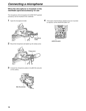
... use The microphone of the microphone kit AJ-MC700P (optional accessory) can be mounted on the viewfinder. 1 Open the microphone holder. 4 If the audio channel whose signals are to be recorded so requires, set the AUDIO IN switch to the MIC IN connector on the camera. Microphone holder 2 Mount the microphone and tighten up the clamp screw. INCOM1 INCOM2 POWER BREAKER RET CONT SEE MANUAL CCU...
... use The microphone of the microphone kit AJ-MC700P (optional accessory) can be mounted on the viewfinder. 1 Open the microphone holder. 4 If the audio channel whose signals are to be recorded so requires, set the AUDIO IN switch to the MIC IN connector on the camera. Microphone holder 2 Mount the microphone and tighten up the clamp screw. INCOM1 INCOM2 POWER BREAKER RET CONT SEE MANUAL CCU...
AKHC930 User Guide
Page 16
... CARD CARD RESET HEAD POWER ALL ALARM REF FILE LOCAL ALL REF STORE STORE CLOSE BAR TEST WHITE AUTO BLACK SET UP PM R WFM R 1 MONITOR G B MONITOR G B SCENE FILE 2 3 SEC ENC SEC ENC 4 STORE 5 6 SHUTTER/VAR ON VAR 7 8 M-GAIN ND HEAD CAP 100 25 6.3 1.6 CC 1.1 4.3 6.3 8.0 CALL ACTIVE AUTO COASER MEMO LENS EXT X0. 8 MEMO RECALL RECALL M-PED IRIS Masler Setup Unit AK-MSU930 Master setup unit AK-MSU930P Microphone...
... CARD CARD RESET HEAD POWER ALL ALARM REF FILE LOCAL ALL REF STORE STORE CLOSE BAR TEST WHITE AUTO BLACK SET UP PM R WFM R 1 MONITOR G B MONITOR G B SCENE FILE 2 3 SEC ENC SEC ENC 4 STORE 5 6 SHUTTER/VAR ON VAR 7 8 M-GAIN ND HEAD CAP 100 25 6.3 1.6 CC 1.1 4.3 6.3 8.0 CALL ACTIVE AUTO COASER MEMO LENS EXT X0. 8 MEMO RECALL RECALL M-PED IRIS Masler Setup Unit AK-MSU930 Master setup unit AK-MSU930P Microphone...
AKHC930 User Guide
Page 17
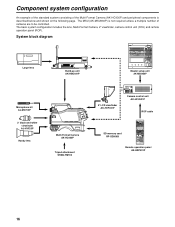
... 18 to the CCU using an optical fiber cable (optional accessory). Thereby, it can also support HD video input and output by connecting the HD output unit (AK-HHD931P). 2 Remote operation panel (ROP: AK-HRP931P) The ROP is connected to 20 for the Multi-Format Camera. It can operate up to the ON position. It can be connected afterward), set the CCU's main power switch to 15 units...
... 18 to the CCU using an optical fiber cable (optional accessory). Thereby, it can also support HD video input and output by connecting the HD output unit (AK-HHD931P). 2 Remote operation panel (ROP: AK-HRP931P) The ROP is connected to 20 for the Multi-Format Camera. It can operate up to the ON position. It can be connected afterward), set the CCU's main power switch to 15 units...
AKHC930 User Guide
Page 18
... ON LOW OUTPUT CAM W.BAL B MID BAR A STBY SAVE HIGH TEST PRST PTT USER SEL Multi-Format Camera AK-HC930P CABLE OPEN SHORT ALARM FUSE 125V 5A FUSE 250V 2.5A TALLY/CALL MAIN HEAD POWER LEVEL COXN PGN1 PGN OFF PGN2 PUSH PRIVATE MIC ON OFF PTT Camera control unit AK-HCU931P ROP cable ROP ON HEAD ON VFPW CAMERA NO. CLOSE BAR TEST WHITE SD CARD AUTO BLACK SET UP CHARACTER...
... ON LOW OUTPUT CAM W.BAL B MID BAR A STBY SAVE HIGH TEST PRST PTT USER SEL Multi-Format Camera AK-HC930P CABLE OPEN SHORT ALARM FUSE 125V 5A FUSE 250V 2.5A TALLY/CALL MAIN HEAD POWER LEVEL COXN PGN1 PGN OFF PGN2 PUSH PRIVATE MIC ON OFF PTT Camera control unit AK-HCU931P ROP cable ROP ON HEAD ON VFPW CAMERA NO. CLOSE BAR TEST WHITE SD CARD AUTO BLACK SET UP CHARACTER...
AKHC930 User Guide
Page 19
... OUTPUT CAM W.BAL B MID BAR A STBY SAVE HIGH TEST PRST PTT USER SEL Multi-Format Camera AK-HC930P 8z LCD viewfinder AK-HVF931P CABLE OPEN SHORT ALARM FUSE 125V 5A FUSE 250V 2.5A TALLY/CALL MAIN HEAD POWER LEVEL COXN PGN1 PGN OFF PGN2 PUSH PRIVATE MIC ON OFF PTT Camera control unit AK-HCU931P ROP cable ROP ON HEAD ON VFPW CAMERA NO. CLOSE BAR TEST WHITE SD CARD AUTO BLACK SET...
... OUTPUT CAM W.BAL B MID BAR A STBY SAVE HIGH TEST PRST PTT USER SEL Multi-Format Camera AK-HC930P 8z LCD viewfinder AK-HVF931P CABLE OPEN SHORT ALARM FUSE 125V 5A FUSE 250V 2.5A TALLY/CALL MAIN HEAD POWER LEVEL COXN PGN1 PGN OFF PGN2 PUSH PRIVATE MIC ON OFF PTT Camera control unit AK-HCU931P ROP cable ROP ON HEAD ON VFPW CAMERA NO. CLOSE BAR TEST WHITE SD CARD AUTO BLACK SET...
AKHC930 User Guide
Page 20
... ON LOW OUTPUT CAM W.BAL B MID BAR A STBY SAVE HIGH TEST PRST PTT USER SEL Multi-Format Camera AK-HC930P CABLE OPEN SHORT ALARM FUSE 125V 5A FUSE 250V 2.5A TALLY/CALL MAIN HEAD POWER LEVEL COXN PGN1 PGN OFF PGN2 PUSH PRIVATE MIC ON OFF PTT Camera control unit 15 AK-HCU931P Large lens Build-up unit AK-HBU931P • A multiple number of cameras (up to...
... ON LOW OUTPUT CAM W.BAL B MID BAR A STBY SAVE HIGH TEST PRST PTT USER SEL Multi-Format Camera AK-HC930P CABLE OPEN SHORT ALARM FUSE 125V 5A FUSE 250V 2.5A TALLY/CALL MAIN HEAD POWER LEVEL COXN PGN1 PGN OFF PGN2 PUSH PRIVATE MIC ON OFF PTT Camera control unit 15 AK-HCU931P Large lens Build-up unit AK-HBU931P • A multiple number of cameras (up to...
AKHC930 User Guide
Page 21
... adjustments, and the adjustment results appear here for about 3 seconds. _Display items and where the items appear 1 Extender display 2 Shutter speed/mode display 3 RET SEL display 4 Battery voltage display 5 Filter display 6 White balance memory display 7 Gain display 8 Audio CH1 and CH2 displays 9 Iris f-number display : Camera warning or message display ; A: The WHITE BAL switch is being used . = MONI SEL display: This indicates the video mode of the monitor output. > Optical level display: This indicates the light sensing level of the optical fiber cable. 21 This display...
... adjustments, and the adjustment results appear here for about 3 seconds. _Display items and where the items appear 1 Extender display 2 Shutter speed/mode display 3 RET SEL display 4 Battery voltage display 5 Filter display 6 White balance memory display 7 Gain display 8 Audio CH1 and CH2 displays 9 Iris f-number display : Camera warning or message display ; A: The WHITE BAL switch is being used . = MONI SEL display: This indicates the video mode of the monitor output. > Optical level display: This indicates the light sensing level of the optical fiber cable. 21 This display...

AKHC930 User Guide
Page 22
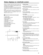
Menu operations Basic setting menu operations _ Displaying the menus User menu 1 Press the MENU button. VF Setting1 Side Modulation 15 Zone Mark 13:9 Safety Mark 16:9 Center Mark OFF Center Mark Sel 1 Line Width 4 3 Turn the JOG dial to access that if, in mind that item's menu. USER MENU Operation Painting Maintenance _ Entering the menu data After accessing the item menus, enter the respective data. 1 Turn the JOG dial to select the...
Menu operations Basic setting menu operations _ Displaying the menus User menu 1 Press the MENU button. VF Setting1 Side Modulation 15 Zone Mark 13:9 Safety Mark 16:9 Center Mark OFF Center Mark Sel 1 Line Width 4 3 Turn the JOG dial to access that if, in mind that item's menu. USER MENU Operation Painting Maintenance _ Entering the menu data After accessing the item menus, enter the respective data. 1 Turn the JOG dial to select the...

AKHC930 User Guide
Page 24
... voltage display to ON or OFF) COLOR TEMP (for setting the color temperature display to ON or OFF) White Ch (for setting the white balance memory) FAN POWER (for setting the camera fan to ON or OFF) FAN MODE (for setting the camera fan mode) USER SW (for setting the user switch) OUTPUT SEL (for setting the analog output to Y/Pb/Pr or RGB) H PHASE (for setting the horizontal phase) CABLE COMP (for setting the analog output cable compensation...
... voltage display to ON or OFF) COLOR TEMP (for setting the color temperature display to ON or OFF) White Ch (for setting the white balance memory) FAN POWER (for setting the camera fan to ON or OFF) FAN MODE (for setting the camera fan mode) USER SW (for setting the user switch) OUTPUT SEL (for setting the analog output to Y/Pb/Pr or RGB) H PHASE (for setting the horizontal phase) CABLE COMP (for setting the analog output cable compensation...

AKHC930 User Guide
Page 26
... Date/Time Camera s internal calendar function settings SD CARD SD card operations with the camera MODE (for selecting the format, load or storage mode) FILE No (for setting the file number to be used) EXECUTE (for executing card operations) FORM CONV Camera s built-in downconverter settings MODE (for setting the down-converter mode) Iris Cont Auto Iris Window Select Iris Level Pear/Ratio A.Iris Range (for setting the range of adjusting fine auto iris level with iris volume joystick) A.Iris Speed (for setting the auto iris speed...
... Date/Time Camera s internal calendar function settings SD CARD SD card operations with the camera MODE (for selecting the format, load or storage mode) FILE No (for setting the file number to be used) EXECUTE (for executing card operations) FORM CONV Camera s built-in downconverter settings MODE (for setting the down-converter mode) Iris Cont Auto Iris Window Select Iris Level Pear/Ratio A.Iris Range (for setting the range of adjusting fine auto iris level with iris volume joystick) A.Iris Speed (for setting the auto iris speed...

AKHC930 User Guide
Page 29
..., HIGH 7) Output selection: CAM, BAR, TEST 8) White balance mode: A, B, preset 9) Shutter speed selection: 1/100, 1/125 1/250, 1/500, 1/1000, 1/2000 10) AWB, ABB settings 11) Menu selection 12) CALL SW 13) INCOM: MIC ON/OFF, receive or PGM level 14) MIC setting: MIC power, MIC gain, MIC1 selection 15) Optical filter setting: REM, LOCAL selection and LOCAL setting *When the CCU is controlled separately for 6) to change without notice. 29 Operating temperature...
..., HIGH 7) Output selection: CAM, BAR, TEST 8) White balance mode: A, B, preset 9) Shutter speed selection: 1/100, 1/125 1/250, 1/500, 1/1000, 1/2000 10) AWB, ABB settings 11) Menu selection 12) CALL SW 13) INCOM: MIC ON/OFF, receive or PGM level 14) MIC setting: MIC power, MIC gain, MIC1 selection 15) Optical filter setting: REM, LOCAL selection and LOCAL setting *When the CCU is controlled separately for 6) to change without notice. 29 Operating temperature...


