

AJHDC27V User Guide
Page 1
Camera/VTR AJ- P Operating Instructions
Camera/VTR AJ- P Operating Instructions
AJHDC27V User Guide
Page 3
Contents Introduction 5 Features 5 Features of the camera unit 5 Features of the VTR unit 7 System configuration 8 Parts and their functions 9 Power supply section 9 Accessory ... 19 Time code related section 19 Power supply 21 Using the Anton/Bauer battery pack 21 Using the Panasonic AU-BP402 battery pack . . .22 Using the Sony NP-1 battery pack 23 Using the Sony... change messages . . .43 Switching the display mode 44 Setting the marker displays 44 Setting the camera ID 44 Screen displays 45 Remaining battery charge and audio channel level and remaining tape displays 45 Displays...
Contents Introduction 5 Features 5 Features of the camera unit 5 Features of the VTR unit 7 System configuration 8 Parts and their functions 9 Power supply section 9 Accessory ... 19 Time code related section 19 Power supply 21 Using the Anton/Bauer battery pack 21 Using the Panasonic AU-BP402 battery pack . . .22 Using the Sony NP-1 battery pack 23 Using the Sony... change messages . . .43 Switching the display mode 44 Setting the marker displays 44 Setting the camera ID 44 Screen displays 45 Remaining battery charge and audio channel level and remaining tape displays 45 Displays...

AJHDC27V User Guide
Page 4
... screen 85 CAM MAIN MENU 2 VF DISPLAY screen 86 VF MARKER screen 86 VF INDICATOR screen 87 CAMERA ID screen 87 SHUTTER SPEED screen 88 !LED screen 88 CAMERA SW MODE screen 89 SUPER GAIN screen 89 FRAME MODE screen 89 CAM MAIN MENU 3 CAM CARD READ/WRITE screen 90 ...screen 105 BATTERY/TAPE screen 105 VTR VF INDICATOR screen 106 MIC/AUDIO screen 106 TC/UB screen 106 Warning system 107 Emergency eject 109 Error codes 109 Maintenance 110 Condensation 110 Head cleaning 110 Cleaning inside the viewfinder 110 Phenomena inherent to CCD cameras 110 Replacing the backup battery 110...
... screen 85 CAM MAIN MENU 2 VF DISPLAY screen 86 VF MARKER screen 86 VF INDICATOR screen 87 CAMERA ID screen 87 SHUTTER SPEED screen 88 !LED screen 88 CAMERA SW MODE screen 89 SUPER GAIN screen 89 FRAME MODE screen 89 CAM MAIN MENU 3 CAM CARD READ/WRITE screen 90 ...screen 105 BATTERY/TAPE screen 105 VTR VF INDICATOR screen 106 MIC/AUDIO screen 106 TC/UB screen 106 Warning system 107 Emergency eject 109 Error codes 109 Maintenance 110 Condensation 110 Head cleaning 110 Cleaning inside the viewfinder 110 Phenomena inherent to CCD cameras 110 Replacing the backup battery 110...
AJHDC27V User Guide
Page 5
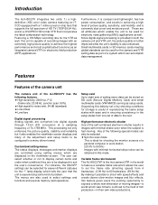
... compression technology. lamp display which was hitherto confined to express a whole new dimension of film production-in this unit is the first camera/VTR in a menu-driven format. Any of 74.1758 MHz. The menus are converted into digital signals through 10-bit A/D conversion at... a sampling frequency of the following features. Featuring a 100 Mbps recording rate for the VTR as an integrated camera/VTR for shooting the monitor screens of recording images with an extremely high picture quality to display certain items and under what conditions...
... compression technology. lamp display which was hitherto confined to express a whole new dimension of film production-in this unit is the first camera/VTR in a menu-driven format. Any of 74.1758 MHz. The menus are converted into digital signals through 10-bit A/D conversion at... a sampling frequency of the following features. Featuring a 100 Mbps recording rate for the VTR as an integrated camera/VTR for shooting the monitor screens of recording images with an extremely high picture quality to display certain items and under what conditions...
AJHDC27V User Guide
Page 6
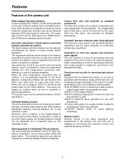
... is used for a total of the high signal-to be selected using the setting menu and GAIN switch. Two independent sets of the camera unit Wide-ranging video gain selection A value ranging from -6 dB to the subject's brightness and color temperature can be displayed as a ...automatic aperture adjustment can easily be finely adjusted by connecting the extension control unit (optional accessory AJ-EC3). 6 Generation of the camera unit and VTR unit is automatically adjusted to guarantee that the need for the balance to store the white balance, and it is enabled by performing...
... is used for a total of the high signal-to be selected using the setting menu and GAIN switch. Two independent sets of the camera unit Wide-ranging video gain selection A value ranging from -6 dB to the subject's brightness and color temperature can be displayed as a ...automatic aperture adjustment can easily be finely adjusted by connecting the extension control unit (optional accessory AJ-EC3). 6 Generation of the camera unit and VTR unit is automatically adjusted to guarantee that the need for the balance to store the white balance, and it is enabled by performing...
AJHDC27V User Guide
Page 7
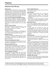
...to record those precious moments-a failure that occurs when recording is resumed after it has been shut down . Tape management information This camera/VTR automatically stores as an interview microphone. Scene-to-scene continuity Simply by controlling the start of the cut is clearly judged to be... By cutting down when the cable has not been connected so that the unit's power can be deleted. Features Features of the VTR unit Digital system The pictures are compressed by a component digital recording system that uses the latest compression technology while non-compression PCM ...
...to record those precious moments-a failure that occurs when recording is resumed after it has been shut down . Tape management information This camera/VTR automatically stores as an interview microphone. Scene-to-scene continuity Simply by controlling the start of the cut is clearly judged to be... By cutting down when the cable has not been connected so that the unit's power can be deleted. Features Features of the VTR unit Digital system The pictures are compressed by a component digital recording system that uses the latest compression technology while non-compression PCM ...
AJHDC27V User Guide
Page 8
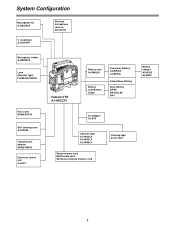
.../CANON Rain cover SHAN-RC700 Soft carrying case AJ-SC900 Tripod mount adapter SHAN-TM700 Extension control unit AJ-EC3 Camera/VTR AJ-HDC27V Battery case AU-M402H Battery case/Battery holder Panasonic Battery AU-BP402 AJ-BP490 Anton/Bauer Battery Sony Battery BP-90 BP-L60/L90 NP-1 Battery charger AG-B425...
.../CANON Rain cover SHAN-RC700 Soft carrying case AJ-SC900 Tripod mount adapter SHAN-TM700 Extension control unit AJ-EC3 Camera/VTR AJ-HDC27V Battery case AU-M402H Battery case/Battery holder Panasonic Battery AU-BP402 AJ-BP490 Anton/Bauer Battery Sony Battery BP-90 BP-L60/L90 NP-1 Battery charger AG-B425...

AJHDC27V User Guide
Page 12
Parts and their functions Viewfinder section >
Parts and their functions Viewfinder section >
AJHDC27V User Guide
Page 14
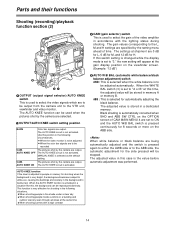
...BAL switch (3) is used to select the video signals which are being automatically adjusted and the switch is used when the pictures shot by the camera are specified by the camera are 0 dB for L, 6 dB for M, and 12 dB for H. When white balance or black balance are to be output from ...the camera unit to the VTR unit, viewfinder and video monitor. Parts and their functions Shooting (recording)/playback function section (2) 5 GAIN (gain selector) switch This is pressed again to either the...
...BAL switch (3) is used to select the video signals which are being automatically adjusted and the switch is used when the pictures shot by the camera are specified by the camera are 0 dB for L, 6 dB for M, and 12 dB for H. When white balance or black balance are to be output from ...the camera unit to the VTR unit, viewfinder and video monitor. Parts and their functions Shooting (recording)/playback function section (2) 5 GAIN (gain selector) switch This is pressed again to either the...

AJHDC27V User Guide
Page 15
When the SDI switch is at all times. When the SDI switch is at "EE," the camera video signals are output at "EE/PB," the EE video and EE audio signals will be output during recording and the playback video and playback ...
When the SDI switch is at all times. When the SDI switch is at "EE," the camera video signals are output at "EE/PB," the EE video and EE audio signals will be output during recording and the playback video and playback ...

AJHDC27V User Guide
Page 17
... minutes, it is pressed during playback, the tape will be reviewed (rewound and played back) at the same time: this button is held down, the camera's setting mode is pressed during playback, the tape will cause the cassette to be ejected. The button's lamp comes on during rewinding. If the unit... (STOP) mode. Parts and their functions Shooting (recording)/playback function section (5) @AB CD > E ? > MODE CHECK button While this will be allocated to each of the camera. ?
... minutes, it is pressed during playback, the tape will be reviewed (rewound and played back) at the same time: this button is held down, the camera's setting mode is pressed during playback, the tape will cause the cassette to be ejected. The button's lamp comes on during rewinding. If the unit... (STOP) mode. Parts and their functions Shooting (recording)/playback function section (5) @AB CD > E ? > MODE CHECK button While this will be allocated to each of the camera. ?
AJHDC27V User Guide
Page 19
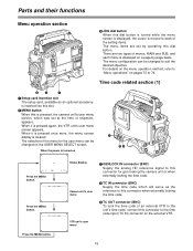
...1 Setup card insertion slot The setup card, available as an optional accessory, is inserted into this slot. 2 MENU button When this is pressed, the camera unit's user menu screen, which will serve as the reference to this connector when externally locking the time code. 3 TC OUT connector (BNC) To ... Press the MENU button. ¢¢¢¢ CAM USER MENU ¢¢¢¢ Camera unit's user menu Press the MENU button. ¢¢¢¢ VTR USER MENU ¢¢¢¢ VTR unit's user menu 1 GENLOCK IN connector (BNC) Supply the analog HD reference signal to this ...
...1 Setup card insertion slot The setup card, available as an optional accessory, is inserted into this slot. 2 MENU button When this is pressed, the camera unit's user menu screen, which will serve as the reference to this connector when externally locking the time code. 3 TC OUT connector (BNC) To ... Press the MENU button. ¢¢¢¢ CAM USER MENU ¢¢¢¢ Camera unit's user menu Press the MENU button. ¢¢¢¢ VTR USER MENU ¢¢¢¢ VTR unit's user menu 1 GENLOCK IN connector (BNC) Supply the analog HD reference signal to this ...

AJHDC27V User Guide
Page 25
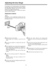
Lens flange back adjustment 2. Lens auto iris operating speed adjustment 3. OThe following lens adjustments and camera adjustments may be necessary depending on the unit) 3 Push down the lever for securing the lens to secure the lens. 25 Mark LENS socket OFor ...
Lens flange back adjustment 2. Lens auto iris operating speed adjustment 3. OThe following lens adjustments and camera adjustments may be necessary depending on the unit) 3 Push down the lever for securing the lens to secure the lens. 25 Mark LENS socket OFor ...
AJHDC27V User Guide
Page 26
... done, it need not be marked as F.b (flange back) ring. 7 Set the zoom ring to the wide-angle position, and turn the F.f ring to the camera.
... done, it need not be marked as F.b (flange back) ring. 7 Set the zoom ring to the wide-angle position, and turn the F.f ring to the camera.

AJHDC27V User Guide
Page 27
... setting mode) 3Press the MENU button and close the menu screen. 4 Set the ZEBRA switch on the viewfinder to ON. 1 Attach the lens to the camera. OSince unevenness in the lighting will make it impossible for the white shading adjustments with most lenses. also when the lens aperture is not indicative...
... setting mode) 3Press the MENU button and close the menu screen. 4 Set the ZEBRA switch on the viewfinder to ON. 1 Attach the lens to the camera. OSince unevenness in the lighting will make it impossible for the white shading adjustments with most lenses. also when the lens aperture is not indicative...

AJHDC27V User Guide
Page 29
Adjusting the viewfinder (The viewfinder is an optional accessory.) Attaching the viewfinder Detaching the viewfinder 1 1 Check that the camera's POWER switch is at OFF. 2 Connect the plug to the viewfinder connecting terminal. Use both hands to the viewfinder connecting terminal, push... out. It may not be possible to remove the viewfinder smoothly with one hand, which may cause damage to it out. Check that the camera's POWER switch is at OFF. Stopper screw 3 Push the viewfinder down. 3 Disconnect the plug from the viewfinder connecting terminal. 4 Tighten the stopper...
Adjusting the viewfinder (The viewfinder is an optional accessory.) Attaching the viewfinder Detaching the viewfinder 1 1 Check that the camera's POWER switch is at OFF. 2 Connect the plug to the viewfinder connecting terminal. Use both hands to the viewfinder connecting terminal, push... out. It may not be possible to remove the viewfinder smoothly with one hand, which may cause damage to it out. Check that the camera's POWER switch is at OFF. Stopper screw 3 Push the viewfinder down. 3 Disconnect the plug from the viewfinder connecting terminal. 4 Tighten the stopper...

AJHDC27V User Guide
Page 31
AJ-HVF27P 4 Set the AUDIO IN switch or switches to "FRONT" in accordance with the audio channel or channels whose sound is to be attached to the viewfinder. 1 Open the mic holder. Audio input preparation When attaching a microphone to the viewfinder (optional accessory) for use The microphone of the AJ-MC700P mic kit (optional accessory) can be recorded. AUDIO IN switches MIC IN jack 31 Locking screw 3 Connect the microphone's connecting cable to the MIC IN jack on the camera. Mic holder 2 Attach the microphone, and tighten the locking screw.
AJ-HVF27P 4 Set the AUDIO IN switch or switches to "FRONT" in accordance with the audio channel or channels whose sound is to be attached to the viewfinder. 1 Open the mic holder. Audio input preparation When attaching a microphone to the viewfinder (optional accessory) for use The microphone of the AJ-MC700P mic kit (optional accessory) can be recorded. AUDIO IN switches MIC IN jack 31 Locking screw 3 Connect the microphone's connecting cable to the MIC IN jack on the camera. Mic holder 2 Attach the microphone, and tighten the locking screw.

AJHDC27V User Guide
Page 32
... holder, and tighten the locking screw. Screws provided with mic holder 5 Set the AUDIO IN switch or switches to the MIC IN jack on the camera.
... holder, and tighten the locking screw. Screws provided with mic holder 5 Set the AUDIO IN switch or switches to the MIC IN jack on the camera.

AJHDC27V User Guide
Page 33
... is supported. 33 AUDIO IN connectors 2 Set the AUDIO IN switch or switches for the channel or channels to the AUDIO IN connector on the camera. 1 Connect the microphone's connecting cable to which supports the phantom power supply system. Audio input preparation When connecting a microphone to the MIC IN jack When...
... is supported. 33 AUDIO IN connectors 2 Set the AUDIO IN switch or switches for the channel or channels to the AUDIO IN connector on the camera. 1 Connect the microphone's connecting cable to which supports the phantom power supply system. Audio input preparation When connecting a microphone to the MIC IN jack When...

AJHDC27V User Guide
Page 34
... the audio component using the XLR cable. 2 Align the grooves in the camera attachment with the wireless receiver using a wireless microphone When connecting audio components Attach the WX-RJ700 wireless receiver when Panasonic's wireless system is to be used. 1 Attach the WX-RJ700 wireless receiver to disengage it. to the operating instructions...
... the audio component using the XLR cable. 2 Align the grooves in the camera attachment with the wireless receiver using a wireless microphone When connecting audio components Attach the WX-RJ700 wireless receiver when Panasonic's wireless system is to be used. 1 Attach the WX-RJ700 wireless receiver to disengage it. to the operating instructions...


