

AJD610WA User Guide
Page 1
P Operating Instructions Digital Camera/VTR AJ-
P Operating Instructions Digital Camera/VTR AJ-
AJD610WA User Guide
Page 3
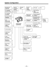
... Code-Related Section 20 ÁWarning/Status Display Section . . . . . 22 Power Supply ÁUsing an Anton Bauer Battery Pack 23 ÁUsing the Panasonic AU-BP402 Battery Pack 24 ÁUsing a Sony Battery Pack 26 ÁUsing the Sony BP-90 Battery Pack 27 ÁUsing the Sony BP... Message 61 ÁChanging the Display Mode 62 ÁSetting the Marker Displays 62 ÁSetting the Camera ID 63 Displays ÁRemaining Battery Level and Audio Level Displays 64 ÁVTR Section Operation/Status-Related Displays 64 ÁTime Code-Related Displays 65 Adjusting the Time and Date 66...
... Code-Related Section 20 ÁWarning/Status Display Section . . . . . 22 Power Supply ÁUsing an Anton Bauer Battery Pack 23 ÁUsing the Panasonic AU-BP402 Battery Pack 24 ÁUsing a Sony Battery Pack 26 ÁUsing the Sony BP-90 Battery Pack 27 ÁUsing the Sony BP... Message 61 ÁChanging the Display Mode 62 ÁSetting the Marker Displays 62 ÁSetting the Camera ID 63 Displays ÁRemaining Battery Level and Audio Level Displays 64 ÁVTR Section Operation/Status-Related Displays 64 ÁTime Code-Related Displays 65 Adjusting the Time and Date 66...
AJD610WA User Guide
Page 4
...193;MAIN menu screen 2 of 4 (SUB menu 121 VF DISPLAY (121), VF INDICATOR (123), CAMERA ID (124), SHUTTER SPEED (124), SYNCHRO SCAN (125), !LED (125), CAMERA SW MODE (126), SUPER GAIN (127), VTR FUNCTION (128), BATT/TAPE ALARM (130) ÁMAIN menu screen 3 of 4 (SUB menu ...Inspection Preparations 151 ÁInspecting the Camera Section 151 ÁInspecting the Viewfinder 152 ÁInspecting the Iris and Zoom Functions 153 ÁInspecting the VTR Section 153 Specifications ÁGeneral 155 ÁCamera Section 155 ÁViewfinder 155 ÁVTR Section 156 ÁAccessories 156 &#...
...193;MAIN menu screen 2 of 4 (SUB menu 121 VF DISPLAY (121), VF INDICATOR (123), CAMERA ID (124), SHUTTER SPEED (124), SYNCHRO SCAN (125), !LED (125), CAMERA SW MODE (126), SUPER GAIN (127), VTR FUNCTION (128), BATT/TAPE ALARM (130) ÁMAIN menu screen 3 of 4 (SUB menu ...Inspection Preparations 151 ÁInspecting the Camera Section 151 ÁInspecting the Viewfinder 152 ÁInspecting the Iris and Zoom Functions 153 ÁInspecting the VTR Section 153 Specifications ÁGeneral 155 ÁCamera Section 155 ÁViewfinder 155 ÁVTR Section 156 ÁAccessories 156 &#...
AJD610WA User Guide
Page 5
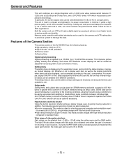
Both the camera unit and VTR unit feature digital signal processing to menus. This improves picture quality, stability and ... provides images with built-in itself is compact and lightweight, its power consumption is digitized by a 18 MHz (typ.) 10-bit AD/DA converter. As a camera with high vertical resolution compared to be selected. ÁSynchro scan mode: This ...cards complying with little noise to manage the data. Setting menu The setting menu is suited for the camera and VTR setting data to provide a system to be obtained even when the gain is required to PCMCIA standard...
Both the camera unit and VTR unit feature digital signal processing to menus. This improves picture quality, stability and ... provides images with built-in itself is compact and lightweight, its power consumption is digitized by a 18 MHz (typ.) 10-bit AD/DA converter. As a camera with high vertical resolution compared to be selected. ÁSynchro scan mode: This ...cards complying with little noise to manage the data. Setting menu The setting menu is suited for the camera and VTR setting data to provide a system to be obtained even when the gain is required to PCMCIA standard...

AJD610WA User Guide
Page 6
...finely adjusted by the character display inside the viewfinder. In addition, when using an Anton Bauer Digital Magnum series battery as the unit's power supply, the remaining battery level can be automatically ...and ND filters, making a total of SMPTE/SNG color bar and reference audio signals The camera section contains a circuit which generates an SMPTE type color bar signal to facilitate color monitor ...and ND (neutral density) filters are two memory systems for displaying the VTR section status The unit informs of VTR trouble, the end of the subject. Auto close function The unit is ...
...finely adjusted by the character display inside the viewfinder. In addition, when using an Anton Bauer Digital Magnum series battery as the unit's power supply, the remaining battery level can be automatically ...and ND filters, making a total of SMPTE/SNG color bar and reference audio signals The camera section contains a circuit which generates an SMPTE type color bar signal to facilitate color monitor ...and ND (neutral density) filters are two memory systems for displaying the VTR section status The unit informs of VTR trouble, the end of the subject. Auto close function The unit is ...

AJD610WA User Guide
Page 7
..., AQ-EC1) allows a portion of the camera section functions to the main unit using the 26-pin/12-pin output adaptor (option, AJ-YA900P), recording can be easily adjusted at the front panel of the internal VTR. Recording by an external VTR When an external VTR is connected using the AJ-MH700P microphone... holder (option). ÁThe audio CH1 recording level can be operated by the external VTR instead of the unit. Features Audio functions ÁA phantom power supply type super-cardioid microphone (option) can be attached and it can also be...
..., AQ-EC1) allows a portion of the camera section functions to the main unit using the 26-pin/12-pin output adaptor (option, AJ-YA900P), recording can be easily adjusted at the front panel of the internal VTR. Recording by an external VTR When an external VTR is connected using the AJ-MH700P microphone... holder (option). ÁThe audio CH1 recording level can be operated by the external VTR instead of the unit. Features Audio functions ÁA phantom power supply type super-cardioid microphone (option) can be attached and it can also be...
AJD610WA User Guide
Page 9
...) Wireless microphone receiver WX-RA700 Shoulder belt Camera/VTR AJ-D610WA 26P/12P output adaptor AJ-YA900P Battery case SHAN-B220 Battery case AU-M402H Battery case/ Battery holder VTR cable VTR Multi connector cable SHAN-C12TCA Panasonic Battery AU-BP220 Sony Battery NP-1 IDX Battery L-40 Panasonic Battery AU-BP402 Anton Bauer Battery Sony Battery...
...) Wireless microphone receiver WX-RA700 Shoulder belt Camera/VTR AJ-D610WA 26P/12P output adaptor AJ-YA900P Battery case SHAN-B220 Battery case AU-M402H Battery case/ Battery holder VTR cable VTR Multi connector cable SHAN-C12TCA Panasonic Battery AU-BP220 Sony Battery NP-1 IDX Battery L-40 Panasonic Battery AU-BP402 Anton Bauer Battery Sony Battery...
AJD610WA User Guide
Page 14
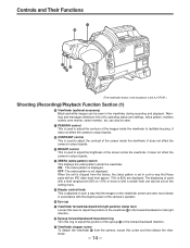
...the viewfinder ¢ from 50% to facilitate focusing. can also be set in the viewfinder during recording and playback. It does not affect the camera's output signals. ¦ ZEBRA (zebra pattern) switch This displays the zebra pattern inside the viewfinder. Warnings and messages relating to adjust the ... those parts with an IRE video level from approx. 70% to 85% are seen most clearly in accordance with the dioptric power of the camera's operator. ¨ Eye cup © Viewfinder forward-backward/left-right position clamp lever Loosen this lever to adjust the position of the viewfinder...
...the viewfinder ¢ from 50% to facilitate focusing. can also be set in the viewfinder during recording and playback. It does not affect the camera's output signals. ¦ ZEBRA (zebra pattern) switch This displays the zebra pattern inside the viewfinder. Warnings and messages relating to adjust the ... those parts with an IRE video level from approx. 70% to 85% are seen most clearly in accordance with the dioptric power of the camera's operator. ¨ Eye cup © Viewfinder forward-backward/left-right position clamp lever Loosen this lever to adjust the position of the viewfinder...
AJD610WA User Guide
Page 16
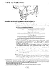
The AUTO KNEE circuit is not activated. The images shot by the camera are output. The gain values corresponding to the L, M and H settings are assigned beforehand on the ... cases: ÁWhen adjusting the video monitor ÁWhen recording color bar signals The images shot by the camera have been selected. È OUTPUT/AUTO KNEE switch setting positions BARS CAM, AUTO KNEE OFF CAM, AUTO KNEE... This is shipped from the factory, these , the background can be output from the camera unit to the VTR unit, viewfinder and video monitor. When the unit is used when the images shot by the...
The AUTO KNEE circuit is not activated. The images shot by the camera are output. The gain values corresponding to the L, M and H settings are assigned beforehand on the ... cases: ÁWhen adjusting the video monitor ÁWhen recording color bar signals The images shot by the camera have been selected. È OUTPUT/AUTO KNEE switch setting positions BARS CAM, AUTO KNEE OFF CAM, AUTO KNEE... This is shipped from the factory, these , the background can be output from the camera unit to the VTR unit, viewfinder and video monitor. When the unit is used when the images shot by the...
AJD610WA User Guide
Page 17
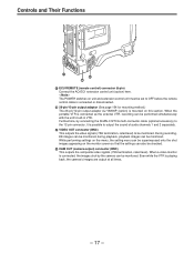
...26-pin/12-pin output adaptor AJ-YA900P (option) is connected, the images shot by the camera can be monitored; When a video monitor is mounted on this section. When the portable VTR is playing back, the camera's images are output at all times. - 17 - Controls and Their Functions µ ∂... appearing on the monitor screen so that the settings can be performed simultaneously with the unit's built-in VTR. during playback, playback images can be checked. ¶ CAM OUT (camera output) connector (BNC) This outputs the composite video signals (75° termination, rated level). Even ...
...26-pin/12-pin output adaptor AJ-YA900P (option) is connected, the images shot by the camera can be monitored; When a video monitor is mounted on this section. When the portable VTR is playing back, the camera's images are output at all times. - 17 - Controls and Their Functions µ ∂... appearing on the monitor screen so that the settings can be performed simultaneously with the unit's built-in VTR. during playback, playback images can be checked. ¶ CAM OUT (camera output) connector (BNC) This outputs the composite video signals (75° termination, rated level). Even ...

AJD610WA User Guide
Page 18
...less power is pressed again, recording stops. It does not affect the camera's output signals. º SUPER GAIN button (inside sliding cover) The super gain mode is forcibly established when this position, the VTR SAVE lamp inside the viewfinder for 3 seconds. This button has the same... Their Functions ∑ Shooting (Recording)/Playback Function Section (4) · VTR START button When this button is kept depressed, the camera's setting status is displayed in the viewfinder. To return to standby mode, press the VTR SAVE/STBY switch once to select SAVE mode, then once again to ...
...less power is pressed again, recording stops. It does not affect the camera's output signals. º SUPER GAIN button (inside sliding cover) The super gain mode is forcibly established when this position, the VTR SAVE lamp inside the viewfinder for 3 seconds. This button has the same... Their Functions ∑ Shooting (Recording)/Playback Function Section (4) · VTR START button When this button is kept depressed, the camera's setting status is displayed in the viewfinder. To return to standby mode, press the VTR SAVE/STBY switch once to select SAVE mode, then once again to ...

AJD610WA User Guide
Page 20
... the setting menu page. Time Code-Related Section (1) É GENLOCK IN/(VIDEO IN) connector (BNC) The reference signal is supplied to this connector when the camera section is to "RET Button" on page 106 for the first time, the first of the item selected on the setting menu by 1 level each...
... the setting menu page. Time Code-Related Section (1) É GENLOCK IN/(VIDEO IN) connector (BNC) The reference signal is supplied to this connector when the camera section is to "RET Button" on page 106 for the first time, the first of the item selected on the setting menu by 1 level each...

AJD610WA User Guide
Page 30
... the lens mount with this unit) - 30 - LENS Connector ÁSee the Handling Instructions provided with the lens for lens handling. |Note{ The lens and camera adjustments listed below may be mounted. 1. Lens auto iris adjustment 3. Lens flange back adjustment 2. Lens Clamping Lever Mount Cap 2 Align the indentation at the top...
... the lens mount with this unit) - 30 - LENS Connector ÁSee the Handling Instructions provided with the lens for lens handling. |Note{ The lens and camera adjustments listed below may be mounted. 1. Lens auto iris adjustment 3. Lens flange back adjustment 2. Lens Clamping Lever Mount Cap 2 Align the indentation at the top...

AJD610WA User Guide
Page 32
... ON. Set ZEBRA1 DETECT to 70%, ZEBRA2 DETECT to 85% and ZEBRA2 to SPOT. (Initial setting mode) Return the MENU SET/OFF switch from the camera's picture quality. Set the viewfinder's ZEBRA switch to L (0 dB). Note: Adjusting the white shad- ing incorrectly will not cover a part of the screen. If any... flickering such as necessary. Flickering occurs easily when fluorescent or mercury lamps, etc. Follow the procedure outlined below when the white shading needs to the camera. In particular, make sure to the VF DISPLAY position.
... ON. Set ZEBRA1 DETECT to 70%, ZEBRA2 DETECT to 85% and ZEBRA2 to SPOT. (Initial setting mode) Return the MENU SET/OFF switch from the camera's picture quality. Set the viewfinder's ZEBRA switch to L (0 dB). Note: Adjusting the white shad- ing incorrectly will not cover a part of the screen. If any... flickering such as necessary. Flickering occurs easily when fluorescent or mercury lamps, etc. Follow the procedure outlined below when the white shading needs to the camera. In particular, make sure to the VF DISPLAY position.

AJD610WA User Guide
Page 33
... lens comes with the 16:9/4:3 mode switch function is no need to A or B execute AWB. The white shading can be used in 4:3 mode, set the camera to open position of light will drop. - 33 - MENU PAGE SHIFT/ITEM 10 When the lens to be adjusted for each of 4 appears. However, this...
... lens comes with the 16:9/4:3 mode switch function is no need to A or B execute AWB. The white shading can be used in 4:3 mode, set the camera to open position of light will drop. - 33 - MENU PAGE SHIFT/ITEM 10 When the lens to be adjusted for each of 4 appears. However, this...
AJD610WA User Guide
Page 41
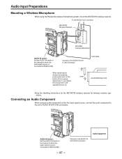
... receiver operations. Connect to the AUDIO IN CH1 or CH2 Connector. To the AUDIO OUT Connector WX-RA700 Wireless Receiver WX-R980 Camera Attachment AUDIO IN switch: Set the AUDIO IN switch of the channel to which the audio signal source is connected to REAR [LINE...]. Connecting an Audio Component When using the Panasonic wireless microphone system, mount the WX-RA700 wireless receiver. AUDIO IN Switch: Set the AUDIO IN Switch of the camera attachment (1) and detach the microphone in the upward direction (2). Audio Equipment Audio ...
... receiver operations. Connect to the AUDIO IN CH1 or CH2 Connector. To the AUDIO OUT Connector WX-RA700 Wireless Receiver WX-R980 Camera Attachment AUDIO IN switch: Set the AUDIO IN switch of the channel to which the audio signal source is connected to REAR [LINE...]. Connecting an Audio Component When using the Panasonic wireless microphone system, mount the WX-RA700 wireless receiver. AUDIO IN Switch: Set the AUDIO IN Switch of the camera attachment (1) and detach the microphone in the upward direction (2). Audio Equipment Audio ...
AJD610WA User Guide
Page 42
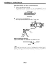
... a tripod, use the accessory tripod attachment. 1 Mount the tripod attachment onto the tripod. Care should be taken as the camera cannot be mounted if the pin remains in consideration of the unit's and tripod attachment's center of gravity. When detaching the tripod attachment Hold down ... grooves until a clicking sound is heard. Red Lever Black Lever |Note{ When the tripod attachment pin does not return to its original position after the camera has been detached, hold down the red lever and move the black lever in the direction of the universal head...
... a tripod, use the accessory tripod attachment. 1 Mount the tripod attachment onto the tripod. Care should be taken as the camera cannot be mounted if the pin remains in consideration of the unit's and tripod attachment's center of gravity. When detaching the tripod attachment Hold down ... grooves until a clicking sound is heard. Red Lever Black Lever |Note{ When the tripod attachment pin does not return to its original position after the camera has been detached, hold down the red lever and move the black lever in the direction of the universal head...
AJD610WA User Guide
Page 46
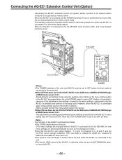
When the AQ-EC1 is connected to an AQ series digital camera. Connecting the AQ-EC1 Extension Control Unit (Option) Connecting the AQ...setting section are saved.) ÁWhen ON has been set for ECU DATA SAVE on the SUB menu CAMERA SW MODE page of MAIN menu screen 2 of 4 The adjustments and settings performed using the switches ... return to the AQ-EC1 settings. (Menu contents set to ON, the unit automatically enters remote control mode. O U T P U T GAIN CAMERA TEST BAR 9 0 -3 (dB) 1/500 1/1000 1/2000 SHUTTER 1/250 ON 1/125 1/100 OFF WHITE BALANCE A B PRE PAINTING AUTO W/B BALANCE...
When the AQ-EC1 is connected to an AQ series digital camera. Connecting the AQ-EC1 Extension Control Unit (Option) Connecting the AQ...setting section are saved.) ÁWhen ON has been set for ECU DATA SAVE on the SUB menu CAMERA SW MODE page of MAIN menu screen 2 of 4 The adjustments and settings performed using the switches ... return to the AQ-EC1 settings. (Menu contents set to ON, the unit automatically enters remote control mode. O U T P U T GAIN CAMERA TEST BAR 9 0 -3 (dB) 1/500 1/1000 1/2000 SHUTTER 1/250 ON 1/125 1/100 OFF WHITE BALANCE A B PRE PAINTING AUTO W/B BALANCE...

AJD610WA User Guide
Page 47
...) ADDITIONAL DTL (117) SKIN TONE DTL (118) KNEE/LEVEL (119) FLARE/GAMMA (120) CAMERA SETTING (120) VF DISPLAY (121) VF INDICATOR (123) CAMERA ID (124) SHUTTER SPEED (124) SYNCHRO SCAN (125) !LED (125) CAMERA SW MODE (126) SUPER GAIN (127) VTR FUNCTION (128) BATT/TAPE ALARM (130) CARD READ/WRITE (131) CARD R/W SELECT (132...
...) ADDITIONAL DTL (117) SKIN TONE DTL (118) KNEE/LEVEL (119) FLARE/GAMMA (120) CAMERA SETTING (120) VF DISPLAY (121) VF INDICATOR (123) CAMERA ID (124) SHUTTER SPEED (124) SYNCHRO SCAN (125) !LED (125) CAMERA SW MODE (126) SUPER GAIN (127) VTR FUNCTION (128) BATT/TAPE ALARM (130) CARD READ/WRITE (131) CARD R/W SELECT (132...

AJD610WA User Guide
Page 52
... bottom of 4 now appears. ¢E E E EMA I N MENU 1 / 4 E E E E ROP MATR I X L OW S E T T I NG M I D SET T I NG H I GH SET T I NG ADD I T I ONA L DT L SK I N TONE DT L KNEE / LEVEL F L A R E / GAMMA CAMERA SET T I N : R PEDESTAL : G PEDESTAL : B PEDESTAL : µ0 0 0 µ0 0 0 . 45 µ0 0 0 µ0 0 0 µ0 0 0 µ0 0 0 µ0 0 0 To display a MAIN menu directly (engineer mode) 1 Set the MENU SET/OFF switch...
... bottom of 4 now appears. ¢E E E EMA I N MENU 1 / 4 E E E E ROP MATR I X L OW S E T T I NG M I D SET T I NG H I GH SET T I NG ADD I T I ONA L DT L SK I N TONE DT L KNEE / LEVEL F L A R E / GAMMA CAMERA SET T I N : R PEDESTAL : G PEDESTAL : B PEDESTAL : µ0 0 0 µ0 0 0 . 45 µ0 0 0 µ0 0 0 µ0 0 0 µ0 0 0 µ0 0 0 To display a MAIN menu directly (engineer mode) 1 Set the MENU SET/OFF switch...


