
AJD610WA User Guide
Page 3
... Viewfinder Screen 57 ÁSelecting Display Items 60 ÁDisplay Mode and Setting Change Message 61 ÁChanging the Display Mode 62 ÁSetting the Marker Displays 62 ÁSetting the Camera ID 63 Displays ÁRemaining Battery Level and Audio Level Displays 64 ÁVTR Section Operation/Status-Related Displays 64 ÁTime Code-Related Displays 65 Adjusting the Time and Date 66 Adjustments and Setup During Recording ÁAdjustments and Setup using the Setting Menu 67 ÁSetting the Gain Selector Value . . . . . 68 ÁSelecting Functions 69...
... Viewfinder Screen 57 ÁSelecting Display Items 60 ÁDisplay Mode and Setting Change Message 61 ÁChanging the Display Mode 62 ÁSetting the Marker Displays 62 ÁSetting the Camera ID 63 Displays ÁRemaining Battery Level and Audio Level Displays 64 ÁVTR Section Operation/Status-Related Displays 64 ÁTime Code-Related Displays 65 Adjusting the Time and Date 66 Adjustments and Setup During Recording ÁAdjustments and Setup using the Setting Menu 67 ÁSetting the Gain Selector Value . . . . . 68 ÁSelecting Functions 69...
AJD610WA User Guide
Page 4
...;Setup Card Data Operations 88 Cassettes ÁInserting and Ejecting Cassettes . . . . 93 ÁPreventing Accidental Erasure 94 Recording ÁBasic Procedures 95 ÁSuccessive Shooting 98 Playback-Checking Recorded Contents ÁRec Review 100 ÁColor Playback 100 Connection With an External VTR. . . . . 101 Recording Simultaneously with the Internal VTR and an External VTR 102 Recording With an External VTR Instead of the Internal VTR ÁUsing the 26-pin/12-pin Output Adaptor 104 RET Button 106 Replacing the Backup Battery 107 Setting Menu Screens 108...
...;Setup Card Data Operations 88 Cassettes ÁInserting and Ejecting Cassettes . . . . 93 ÁPreventing Accidental Erasure 94 Recording ÁBasic Procedures 95 ÁSuccessive Shooting 98 Playback-Checking Recorded Contents ÁRec Review 100 ÁColor Playback 100 Connection With an External VTR. . . . . 101 Recording Simultaneously with the Internal VTR and an External VTR 102 Recording With an External VTR Instead of the Internal VTR ÁUsing the 26-pin/12-pin Output Adaptor 104 RET Button 106 Replacing the Backup Battery 107 Setting Menu Screens 108...
AJD610WA User Guide
Page 5
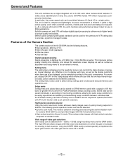
... setting menu and the GAIN switch. High-function electronic shutter Using the built-in standardizing setup conditions between 16:9 and 4:3 in itself is compact and lightweight, its power consumption is minimal, it yields a high picture quality, and it ideal for the camera and VTR setting data to provide a system to manage the data. Setting menu The setting menu is required to operate the Picture Link (Pix Link) function sold as the display...
... setting menu and the GAIN switch. High-function electronic shutter Using the built-in standardizing setup conditions between 16:9 and 4:3 in itself is compact and lightweight, its power consumption is minimal, it yields a high picture quality, and it ideal for the camera and VTR setting data to provide a system to manage the data. Setting menu The setting menu is required to operate the Picture Link (Pix Link) function sold as the display...
AJD610WA User Guide
Page 16
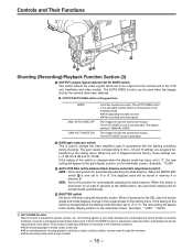
... changed when the display mode has been set to "3", the new setting will appear at the shutter display position on the viewfinder screen. (Example: ":1/250", ":1/60.8") 1) AUTO KNEE function When the level is held down for shooting in the following cases: ÁWhen adjusting the video monitor ÁWhen recording color bar signals The images shot by the camera have been selected. È OUTPUT/AUTO KNEE switch setting positions BARS CAM, AUTO KNEE OFF CAM, AUTO...
... changed when the display mode has been set to "3", the new setting will appear at the shutter display position on the viewfinder screen. (Example: ":1/250", ":1/60.8") 1) AUTO KNEE function When the level is held down for shooting in the following cases: ÁWhen adjusting the video monitor ÁWhen recording color bar signals The images shot by the camera have been selected. È OUTPUT/AUTO KNEE switch setting positions BARS CAM, AUTO KNEE OFF CAM, AUTO...
AJD610WA User Guide
Page 17
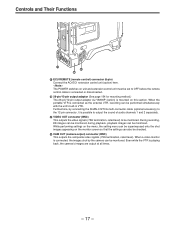
... video signals (75° termination, rated level) to OFF before the remote control cable is connected or disconnected. ´ 26-pin/12-pin output adaptor (See page 104 for mounting method.) The 26-pin/12-pin output adaptor AJ-YA900P (option) is mounted on the monitor screen so that the settings can be monitored. Even while the VTR is connected as the external VTR, recording...
... video signals (75° termination, rated level) to OFF before the remote control cable is connected or disconnected. ´ 26-pin/12-pin output adaptor (See page 104 for mounting method.) The 26-pin/12-pin output adaptor AJ-YA900P (option) is mounted on the monitor screen so that the settings can be monitored. Even while the VTR is connected as the external VTR, recording...

AJD610WA User Guide
Page 22
... lamp does not operate. Ö WARNING lamp This flashes or lights when trouble occurs in the illustration is the AJ-VF10P.) Ñ TCG (time code selector) switch This is used to warn the operator. Controls and Their Functions ' " ' ÷ ◊ ÿ - Set to this window. - 22 - It flashes in progress. " (The viewfinder shown in the VTR section. × LIGHT switch ON: This illuminates the display window Ø. LOW: The...
... lamp does not operate. Ö WARNING lamp This flashes or lights when trouble occurs in the illustration is the AJ-VF10P.) Ñ TCG (time code selector) switch This is used to warn the operator. Controls and Their Functions ' " ' ÷ ◊ ÿ - Set to this window. - 22 - It flashes in progress. " (The viewfinder shown in the VTR section. × LIGHT switch ON: This illuminates the display window Ø. LOW: The...
AJD610WA User Guide
Page 46
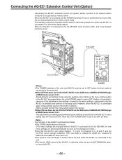
... menu setting section of the AQ-EC1 are set to be used while the AQ-EC1 is connected to the unit. ÁThe lens iris (IRIS) control of the AQ-EC1 is valid only when the lens iris AUTO/MANUAL selector is set for ECU DATA SAVE on the SUB menu CAMERA SW MODE page of MAIN menu screen 2 of 4 ÁAll adjustments and settings made using the switches and controls on the setup card...
... menu setting section of the AQ-EC1 are set to be used while the AQ-EC1 is connected to the unit. ÁThe lens iris (IRIS) control of the AQ-EC1 is valid only when the lens iris AUTO/MANUAL selector is set for ECU DATA SAVE on the SUB menu CAMERA SW MODE page of MAIN menu screen 2 of 4 ÁAll adjustments and settings made using the switches and controls on the setup card...

AJD610WA User Guide
Page 65
... TCG switch position SET F-RUN or R-RUN DISPLAY switch position TC or CTL UB CTL TC UB Displayed item Time code User bit CTL Time code User bit - 65 - Display Time Code-Related Displays DF SLAVE TCG HOLD WIDE EMPHASIS 0 h min s frm 10 E TAPE F 20 E BATT F RF SERVO HUMID SLACK 30 40 CH1 dB CH2 These lamps light to an external source. DF: This lamp lights during drop frame mode...
... TCG switch position SET F-RUN or R-RUN DISPLAY switch position TC or CTL UB CTL TC UB Displayed item Time code User bit CTL Time code User bit - 65 - Display Time Code-Related Displays DF SLAVE TCG HOLD WIDE EMPHASIS 0 h min s frm 10 E TAPE F 20 E BATT F RF SERVO HUMID SLACK 30 40 CH1 dB CH2 These lamps light to an external source. DF: This lamp lights during drop frame mode...

AJD610WA User Guide
Page 67
... required VTR functions Shading adjustment Setup card data operations SHUTTER SPEED SYNCHRO SCAN VTR FUNCTION AUTO SHADING SET UP CARD Operation reference Setting the Gain Selector Value, Setting the DTL and gamma, etc. Setting menu operations are as follows. Adjustment/setup items at the setting menu Adjustment/setup item Setting the gain selector value Page name SETTING (LOW/MID/HIGH) Selecting the shutter speed/ mode to be adjusted or set up at the setting menu. Setting the Electronic Shutter Setting the Electronic Shutter Selecting Functions Shading Adjustment Setup Card Operations...
... required VTR functions Shading adjustment Setup card data operations SHUTTER SPEED SYNCHRO SCAN VTR FUNCTION AUTO SHADING SET UP CARD Operation reference Setting the Gain Selector Value, Setting the DTL and gamma, etc. Setting menu operations are as follows. Adjustment/setup items at the setting menu Adjustment/setup item Setting the gain selector value Page name SETTING (LOW/MID/HIGH) Selecting the shutter speed/ mode to be adjusted or set up at the setting menu. Setting the Electronic Shutter Setting the Electronic Shutter Selecting Functions Shading Adjustment Setup Card Operations...

AJD610WA User Guide
Page 70
... not display these lights appears to be adjusted while the setting menu appears on the viewfinder screen. This gives rise to flicker and to a phenomenon where the hue changes along with the lighting conditions. ¡Refer to the description of the ¨ FILTER knob (page 15) in the Shooting and Recording/ Playback Function Section for a description of setting the display mode. |Notes{ ¡The white balance and black balance...
... not display these lights appears to be adjusted while the setting menu appears on the viewfinder screen. This gives rise to flicker and to a phenomenon where the hue changes along with the lighting conditions. ¡Refer to the description of the ¨ FILTER knob (page 15) in the Shooting and Recording/ Playback Function Section for a description of setting the display mode. |Notes{ ¡The white balance and black balance...
AJD610WA User Guide
Page 73
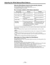
... repeated attempts, consult your dealer. |Notes{ ¡The white balance will not be adjusted while the setting menu is a problem, turn the SHUTTER switch to white balance adjustment Error message COLOR TEMP. There is too high. If flickering is displayed on the "CAMERA SW MODE" SUB menu page of MAIN menu screen 2 of the memories are unstable (shooting is taking place under fluorescent lighting or the camera is limited to the filter. Decrease the illumination...
... repeated attempts, consult your dealer. |Notes{ ¡The white balance will not be adjusted while the setting menu is a problem, turn the SHUTTER switch to white balance adjustment Error message COLOR TEMP. There is too high. If flickering is displayed on the "CAMERA SW MODE" SUB menu page of MAIN menu screen 2 of the memories are unstable (shooting is taking place under fluorescent lighting or the camera is limited to the filter. Decrease the illumination...
AJD610WA User Guide
Page 83
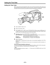
... 4. Setting the Time Data Setting the Time Code When using the SHIFT/ITEM, UP and DOWN buttons. If the time code is set to continue operating for extended periods of the VTR's operation. The time code can be set first, the time code generator will stop while the user bit is pressed, the flashing digit moves to "DF" or "NDF" on the "VTR FUNCTION" SUB menu page of MAIN menu 2 of the flashing digit. Each time it is being set, causing...
... 4. Setting the Time Data Setting the Time Code When using the SHIFT/ITEM, UP and DOWN buttons. If the time code is set to continue operating for extended periods of the VTR's operation. The time code can be set first, the time code generator will stop while the user bit is pressed, the flashing digit moves to "DF" or "NDF" on the "VTR FUNCTION" SUB menu page of MAIN menu 2 of the flashing digit. Each time it is being set, causing...

AJD610WA User Guide
Page 86
... camera's memory, are now loaded, and the settings are completed. 6 Set the MENU SET/OFF switch to load them. Releasing the external lock Stop supplying the external time code and then set the F-RUN/R-RUN switch to recording mode for the time code generator, connect the external power supply to the reference time code. Using the user data The setting menu contents can be re-established without delay. Loading the user data 1 The menu's CARD READ/WRITE screen is used to save the user data. 2 Set the MENU SET/OFF switch...
... camera's memory, are now loaded, and the settings are completed. 6 Set the MENU SET/OFF switch to load them. Releasing the external lock Stop supplying the external time code and then set the F-RUN/R-RUN switch to recording mode for the time code generator, connect the external power supply to the reference time code. Using the user data The setting menu contents can be re-established without delay. Loading the user data 1 The menu's CARD READ/WRITE screen is used to save the user data. 2 Set the MENU SET/OFF switch...

AJD610WA User Guide
Page 91
... UP button is pressed in step 7, the data is not formatted. Setup Card Operations Protecting stored data If the setup card's WRITE PROTECT switch is set to ON. Data writing error messages Error message NO CONFIG NO CARD WRITE PROTECT ERROR Condition The setup card is not written. Insert a card. Set the write protect switch on the side of the card to ON. Countermeasure Format the card. Replace the card. - 91 - A setup card is not inserted. Data cannot be defective. Set to...
... UP button is pressed in step 7, the data is not formatted. Setup Card Operations Protecting stored data If the setup card's WRITE PROTECT switch is set to ON. Data writing error messages Error message NO CONFIG NO CARD WRITE PROTECT ERROR Condition The setup card is not written. Insert a card. Set the write protect switch on the side of the card to ON. Countermeasure Format the card. Replace the card. - 91 - A setup card is not inserted. Data cannot be defective. Set to...

AJD610WA User Guide
Page 101
... 9 CAM MIC (H) 10 CAM MIC (C) 11 CAM MIC (GND) 12 VTR START/STOP 15 REC TALLY 18 RET VIDEO 19 RET VIDEO GND B GND - 101 - Connection With an External VTR The unit is equipped with an interface which enables recording to be performed by the VTR section (internal VTR) of the unit and an external VTR. The BATT lamp and remaining battery level display function inside the viewfinder indicate the REC status of the external VTR. Use this switch...
... 9 CAM MIC (H) 10 CAM MIC (C) 11 CAM MIC (GND) 12 VTR START/STOP 15 REC TALLY 18 RET VIDEO 19 RET VIDEO GND B GND - 101 - Connection With an External VTR The unit is equipped with an interface which enables recording to be performed by the VTR section (internal VTR) of the unit and an external VTR. The BATT lamp and remaining battery level display function inside the viewfinder indicate the REC status of the external VTR. Use this switch...

AJD610WA User Guide
Page 105
... set, the audio output level can be changed to function. The external VTR starts recording. When the built-in place of the internal VTR using the VTR START button on the unit and the VTR button on the lens if the 26P CONTROL function on the "VTR FUNCTION" SUB menu page of the MAIN menu screen 2 of 4 prevents the internal VTR from the internal VTR to the external VTR If the internal VTR should develop a problem (such as indicated above. Starting recording Operate the external VTR to set...
... set, the audio output level can be changed to function. The external VTR starts recording. When the built-in place of the internal VTR using the VTR START button on the unit and the VTR button on the lens if the 26P CONTROL function on the "VTR FUNCTION" SUB menu page of the MAIN menu screen 2 of 4 prevents the internal VTR from the internal VTR to the external VTR If the internal VTR should develop a problem (such as indicated above. Starting recording Operate the external VTR to set...
AJD610WA User Guide
Page 128
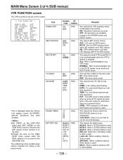
... VTR operation when condensation has formed. This selects 26P remote control. This selects in the STOP (power save) mode and REC PAUSE mode. This sets DF or NDF for the POWER switch and EJECT button. USER: User setting (fixed setting) DATE: For year/month/day/hour realtime operations. This selects the time for the UB MODE item. This selects the battery type. ON: Operation continues as usual. OFF: All operations are set on this screen. ¢| V T R F U N C T I ON { HUM I D OPE : OFF 2 6 P CONTROL : OF F REC...
... VTR operation when condensation has formed. This selects 26P remote control. This selects in the STOP (power save) mode and REC PAUSE mode. This sets DF or NDF for the POWER switch and EJECT button. USER: User setting (fixed setting) DATE: For year/month/day/hour realtime operations. This selects the time for the UB MODE item. This selects the battery type. ON: Operation continues as usual. OFF: All operations are set on this screen. ¢| V T R F U N C T I ON { HUM I D OPE : OFF 2 6 P CONTROL : OF F REC...

AJD610WA User Guide
Page 147
... the VTR stops. Check the error code in the time code display position of trouble. Playback, fast forward and rewind operation stops. Warning System If trouble is detected immediately after the heads are held until the display goes off when tape running stops and the HUMID display does not go off . SERVO Lighted Flashes 4 times per second Flashes 4 times per second Emitted 4 times per second F1) Video head clogging, recording system trouble Head clogging is turned on again, wait until REC/PAUSE mode...
... the VTR stops. Check the error code in the time code display position of trouble. Playback, fast forward and rewind operation stops. Warning System If trouble is detected immediately after the heads are held until the display goes off when tape running stops and the HUMID display does not go off . SERVO Lighted Flashes 4 times per second Flashes 4 times per second Emitted 4 times per second F1) Video head clogging, recording system trouble Head clogging is turned on again, wait until REC/PAUSE mode...

AJD610WA User Guide
Page 153
...- Inspecting the VTR Section (1) Tape Running Inspections 1 Set the VTR SAVE/STBY switch to subjects with the same brightness in accordance with the switch setting. ÁThe gain value display on the viewfinder screen changes in the display window do not light. 6 Press the unit's VTR START button again. Perform "(1) Tape Running Inspections" to electric zoom mode and check the electric zoom operation. Inspections Before Shooting Inspecting the Iris and Zoom Functions 1 Set the zoom to "(4) Earphone...
...- Inspecting the VTR Section (1) Tape Running Inspections 1 Set the VTR SAVE/STBY switch to subjects with the same brightness in accordance with the switch setting. ÁThe gain value display on the viewfinder screen changes in the display window do not light. 6 Press the unit's VTR START button again. Perform "(1) Tape Running Inspections" to electric zoom mode and check the electric zoom operation. Inspections Before Shooting Inspecting the Iris and Zoom Functions 1 Set the zoom to "(4) Earphone...

AJD610WA User Guide
Page 154
... Shooting (2) Inspection of Audio Level Automatic Adjustment Functions 1 Set the AUDIO SELECT CH1/CH2 switch to AUTO. 2 Set the AUDIO IN CH1/CH2 switch to FRONT [MIC]. 3 Aim a microphone connected to the MIC IN jack at a sound source and check that the set user bit is cut off and that the microphone sound can also be heard from the earphone. 4 Turn the MONITOR control and check that the earphone volume changes. (5) Inspections when Using an External Microphone 1 Connect an external microphone to the AUDIO...
... Shooting (2) Inspection of Audio Level Automatic Adjustment Functions 1 Set the AUDIO SELECT CH1/CH2 switch to AUTO. 2 Set the AUDIO IN CH1/CH2 switch to FRONT [MIC]. 3 Aim a microphone connected to the MIC IN jack at a sound source and check that the set user bit is cut off and that the microphone sound can also be heard from the earphone. 4 Turn the MONITOR control and check that the earphone volume changes. (5) Inspections when Using an External Microphone 1 Connect an external microphone to the AUDIO...


