
Owner Manual
Page 1
... the instructions in the unit. AV Receiver TX-NR3007 TX-NR5007 Instruction Manual Thank you to obtain optimum performance and listening enjoyment from your new AV Receiver. Contents Introduction 2 Connection 18 ...Turning On & First Time Setup .....48 Basic Operations 67 Using the Listening Modes ........81 Advanced Setup 92 NET/USB 120 Multi Zone 130 Controlling Other Components....139 Others 154 En Please read this manual thoroughly before making connections and plugging in this manual for purchasing an Onkyo AV Receiver...
... the instructions in the unit. AV Receiver TX-NR3007 TX-NR5007 Instruction Manual Thank you to obtain optimum performance and listening enjoyment from your new AV Receiver. Contents Introduction 2 Connection 18 ...Turning On & First Time Setup .....48 Basic Operations 67 Using the Listening Modes ........81 Advanced Setup 92 NET/USB 120 Multi Zone 130 Controlling Other Components....139 Others 154 En Please read this manual thoroughly before making connections and plugging in this manual for purchasing an Onkyo AV Receiver...

Owner Manual
Page 3
... normal. • If you do not intend to disconnect this equipment does cause harmful interference to radio or television reception, which the receiver is used in a particular installation. If this unit from that to Part 15 of mild detergent and water. For models having a ...receiver. • Connect the equipment into an outlet on the unit's rear panel (e.g., AC 230 V, 50 Hz or AC 120 V, 60 Hz). cian for a long time, because they may leave marks on the unit, contact your hands are designed to provide reasonable protection against harmful interference in your Onkyo...
... normal. • If you do not intend to disconnect this equipment does cause harmful interference to radio or television reception, which the receiver is used in a particular installation. If this unit from that to Part 15 of mild detergent and water. For models having a ...receiver. • Connect the equipment into an outlet on the unit's rear panel (e.g., AC 230 V, 50 Hz or AC 120 V, 60 Hz). cian for a long time, because they may leave marks on the unit, contact your hands are designed to provide reasonable protection against harmful interference in your Onkyo...
Owner Manual
Page 4
... Make sure you have the same ampere rating as that the ONKYO product described in this instruction manual is in the mains lead of this adapter if your AC outlet does not match with the plug on the AV receiver's power cord (adapter varies from country to country.) Speaker cable...the terminals in the plug. Check for the ASTA mark or the BSI mark on packaging, the letter at the end of Conformity We, ONKYO EUROPE ELECTRONICS GmbH LIEGNITZERSTRASSE 6, 82194 GROEBENZELL, GERMANY declare in own responsibility, that indicated on the plug. Use this apparatus may not correspond ...
... Make sure you have the same ampere rating as that the ONKYO product described in this instruction manual is in the mains lead of this adapter if your AC outlet does not match with the plug on the AV receiver's power cord (adapter varies from country to country.) Speaker cable...the terminals in the plug. Check for the ASTA mark or the BSI mark on packaging, the letter at the end of Conformity We, ONKYO EUROPE ELECTRONICS GmbH LIEGNITZERSTRASSE 6, 82194 GROEBENZELL, GERMANY declare in own responsibility, that indicated on the plug. Use this apparatus may not correspond ...
Owner Manual
Page 5
.../USB 120 About NET 120 Connecting the AV Receiver 120 Listening to Internet Radio 121 Playing Music Files on a Server 122 Network Settings 126 About USB 127 Playing Music ...up for Remote Control Code 139 Entering Remote Control Codes 141 Remote Control Codes for Onkyo Components Connected via V 142 Resetting REMOTE MODE Buttons 142 Resetting the Remote Controller ... 152 Using Normal Macros 153 Others Troubleshooting 154 Specifications (TX-NR3007 160 Specifications (TX-NR5007 161 Video Resolution Chart 162 * To reset the AV receiver to its factory defaults, turn it on and, while...
.../USB 120 About NET 120 Connecting the AV Receiver 120 Listening to Internet Radio 121 Playing Music Files on a Server 122 Network Settings 126 About USB 127 Playing Music ...up for Remote Control Code 139 Entering Remote Control Codes 141 Remote Control Codes for Onkyo Components Connected via V 142 Resetting REMOTE MODE Buttons 142 Resetting the Remote Controller ... 152 Using Normal Macros 153 Others Troubleshooting 154 Specifications (TX-NR3007 160 Specifications (TX-NR5007 161 Video Resolution Chart 162 * To reset the AV receiver to its factory defaults, turn it on and, while...

Owner Manual
Page 7
...be registered in the U.S. THX Ultra2 Plus Before any technology or software incorporated in receivers compatible with the SIRIUS or XM Satellite Radio Systems. Service not available in Alaska...and DLNA CERTIFIED™ are trademarks, service marks, or certification marks of the Digital Living Network Alliance." * Re-Equalization and the "Re-EQ" logo are trademarks of quality and performance...Xantech Corporation. * "Niles" is a trademark of this copyright protection technology must install an Onkyo UP-HT1 HD Radio tuner module (sold separately. SIRIUS, XM and all related marks and...
...be registered in the U.S. THX Ultra2 Plus Before any technology or software incorporated in receivers compatible with the SIRIUS or XM Satellite Radio Systems. Service not available in Alaska...and DLNA CERTIFIED™ are trademarks, service marks, or certification marks of the Digital Living Network Alliance." * Re-Equalization and the "Re-EQ" logo are trademarks of quality and performance...Xantech Corporation. * "Niles" is a trademark of this copyright protection technology must install an Onkyo UP-HT1 HD Radio tuner module (sold separately. SIRIUS, XM and all related marks and...
Owner Manual
Page 8
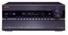
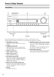
...1, AUX 2, TV/TAPE, TUNER, CD, PHONO, PORT, NET/USB. See "Volume Setup" on page 10. They are used to adjust the volume of the AV receiver to On or Standby. The page numbers in Standby mode, and it . Front & Rear Panels Front Panel B CDEFG H I MASTER VOLUME control (67) and ...indicator This control is used to select from the remote controller. D ZONE 2 indicator (136) Lights when Zone 2 is used to set the AV receiver to -2 dB, -81.5 dB through +18.0 dB (relative display). J PURE AUDIO button (81) Selects the Pure Audio listening mode. Pressing this button again...
...1, AUX 2, TV/TAPE, TUNER, CD, PHONO, PORT, NET/USB. See "Volume Setup" on page 10. They are used to adjust the volume of the AV receiver to On or Standby. The page numbers in Standby mode, and it . Front & Rear Panels Front Panel B CDEFG H I MASTER VOLUME control (67) and ...indicator This control is used to select from the remote controller. D ZONE 2 indicator (136) Lights when Zone 2 is used to set the AV receiver to -2 dB, -81.5 dB through +18.0 dB (relative display). J PURE AUDIO button (81) Selects the Pure Audio listening mode. Pressing this button again...

Owner Manual
Page 10
...outputted for composite video, analog audio, and optical digital audio. " POWER switch (48) (European and Asian models) This is selected. 10 G NETWORK indicator (121) Lights when the Net input selector is the main power switch. LW: Front wide left LH: Front high left RH: Front high... (61, 98): Flashes during Audyssey MultEQ® XT Room Correction and Speaker Setup. Y AUX 1 INPUT (42) This input can be played through the AV receiver. M N O PQ F Listening mode and format indicators (81) Show the selected listening mode and audio input signal format. X USB port (127) A...
...outputted for composite video, analog audio, and optical digital audio. " POWER switch (48) (European and Asian models) This is selected. 10 G NETWORK indicator (121) Lights when the Net input selector is the main power switch. LW: Front wide left LH: Front high left RH: Front high... (61, 98): Flashes during Audyssey MultEQ® XT Room Correction and Speaker Setup. Y AUX 1 INPUT (42) This input can be played through the AV receiver. M N O PQ F Listening mode and format indicators (81) Show the selected listening mode and audio input signal format. X USB port (127) A...

Owner Manual
Page 11
... indicator (23, 25) Lights when the "Speakers Type(FrontA)" or "Speakers Type(FrontB)" setting is set to "BTL" for bridged front speaker operation. Rear Panel (TX-NR5007) * North American models BCDE F G HI JK L M NO P Q R S T U V W X Y Z [ " # $ %* B UNIVERSAL PORT This port is selected...TX-NR5007) These optical digital audio inputs are plugged into the PHONES jack. AUTO (73): Lights when Auto Tuning mode is for connecting components with the Universal Port option such as the audio source: HDMI, ANALOG, or DIGITAL. P MUTING indicator (69) Flashes while the AV receiver...
... indicator (23, 25) Lights when the "Speakers Type(FrontA)" or "Speakers Type(FrontB)" setting is set to "BTL" for bridged front speaker operation. Rear Panel (TX-NR5007) * North American models BCDE F G HI JK L M NO P Q R S T U V W X Y Z [ " # $ %* B UNIVERSAL PORT This port is selected...TX-NR5007) These optical digital audio inputs are plugged into the PHONES jack. AUTO (73): Lights when Auto Tuning mode is for connecting components with the Universal Port option such as the audio source: HDMI, ANALOG, or DIGITAL. P MUTING indicator (69) Flashes while the AV receiver...

Owner Manual
Page 12
...AV receiver's remote controller can assign each one to an input selector to suit your setup. See "HDMI Input Setup" on page 55. They're assignable, which means you can then be connected to an V jack on another Onkyo AV...AV receiver. P AC INLET The supplied power cord is output. 12V TRIGGER OUT ZONE 3 This output can be connected to suit your Ethernet network (e.g., router or switch) for playing music files on a networked...turned on, a 12-volt trigger signal is for connecting the AV receiver to your setup. F USB port (TX-NR5007) A USB mass storage device, such as CD and DVD/BD...
...AV receiver's remote controller can assign each one to an input selector to suit your setup. See "HDMI Input Setup" on page 55. They're assignable, which means you can then be connected to an V jack on another Onkyo AV...AV receiver. P AC INLET The supplied power cord is output. 12V TRIGGER OUT ZONE 3 This output can be connected to suit your Ethernet network (e.g., router or switch) for playing music files on a networked...turned on, a 12-volt trigger signal is for connecting the AV receiver to your setup. F USB port (TX-NR5007) A USB mass storage device, such as CD and DVD/BD...
Owner Manual
Page 13
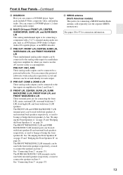
... in Zone 2. The FRONT WIDE/ZONE 2 L/R terminals can be connected to the analog audio input on amplifiers in Zone 3. See pages 18 to use the AV receiver solely as a DVD player, DVD-Audio or Super Audio CD-capable player, or an MPEG decoder. " PRE OUT: FRONT L/R, CENTER, SURR L/R, SURR BACK L/R, and FRONT...
... in Zone 2. The FRONT WIDE/ZONE 2 L/R terminals can be connected to the analog audio input on amplifiers in Zone 3. See pages 18 to use the AV receiver solely as a DVD player, DVD-Audio or Super Audio CD-capable player, or an MPEG decoder. " PRE OUT: FRONT L/R, CENTER, SURR L/R, SURR BACK L/R, and FRONT...

Owner Manual
Page 14
... cover. trol sensor. • When the remote control codes have been registered and you want to operate an Onkyo component without V connection, point the remote controller at the AV receiver's remote con- ler may not work reliably. • Don't put anything, such as shown below. Keep.... • If another component (page 141), or when you want to operate an Onkyo component with the polarity diagram inside the battery compartment. 3 Replace the cover and push it and the AV receiver's remote con- troller, because the buttons may not work reliably, try replacing the batteries...
... cover. trol sensor. • When the remote control codes have been registered and you want to operate an Onkyo component without V connection, point the remote controller at the AV receiver's remote con- ler may not work reliably. • Don't put anything, such as shown below. Keep.... • If another component (page 141), or when you want to operate an Onkyo component with the polarity diagram inside the battery compartment. 3 Replace the cover and push it and the AV receiver's remote con- troller, because the buttons may not work reliably, try replacing the batteries...
Owner Manual
Page 15
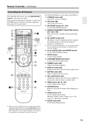
...K DISPLAY button (68) Displays information about eight seconds, press the REMOTE MODE button. C ON button (48) Turns on the AV receiver. I 5 2J Q *1 When you want to change the speaker selection: Front High speakers or Front Wide speakers*2. You can ...the combination of the currently selected remote controller mode. B STANDBY button (48) Sets the AV receiver to select Receiver mode. Remote Controller-Continued Controlling the AV Receiver To control the AV receiver, press the [RECEIVER] button to Standby. Speakers A or Speakers B. *2 If you use surround back speakers,...
...K DISPLAY button (68) Displays information about eight seconds, press the REMOTE MODE button. C ON button (48) Turns on the AV receiver. I 5 2J Q *1 When you want to change the speaker selection: Front High speakers or Front Wide speakers*2. You can ...the combination of the currently selected remote controller mode. B STANDBY button (48) Sets the AV receiver to select Receiver mode. Remote Controller-Continued Controlling the AV Receiver To control the AV receiver, press the [RECEIVER] button to Standby. Speakers A or Speakers B. *2 If you use surround back speakers,...

Owner Manual
Page 16
Remote Controller-Continued ■ Controlling the tuner To control the AV receiver's tuner, press the [TUNER] (or [RECEIVER]) button. Note: An Onkyo cassette recorder connected via V can select a preset directly. button (74) Used to select radio presets. 5 Number buttons (73, 74) Used to tune into radio stations. 2 D.... the Direct tuning mode. You can select AM or FM by pressing the [TUNER] button repeatedly. 1 Arrow [R]/[X] buttons Used to select radio stations directly in Receiver mode (see page 149). 16
Remote Controller-Continued ■ Controlling the tuner To control the AV receiver's tuner, press the [TUNER] (or [RECEIVER]) button. Note: An Onkyo cassette recorder connected via V can select a preset directly. button (74) Used to select radio presets. 5 Number buttons (73, 74) Used to tune into radio stations. 2 D.... the Direct tuning mode. You can select AM or FM by pressing the [TUNER] button repeatedly. 1 Arrow [R]/[X] buttons Used to select radio stations directly in Receiver mode (see page 149). 16

Owner Manual
Page 17
... hall. They significantly enhance the spatial experience. Corner position 17 About Home Theater Enjoying Home Theater Thanks to the AV receiver's superb capabilities, you can enjoy Dolby Pro Logic IIx, DTS Neo:6, or Onkyo's original DSP listening modes. Position them inward so as possible) and at about 2 to 3 feet (60 to 100 cm...
... hall. They significantly enhance the spatial experience. Corner position 17 About Home Theater Enjoying Home Theater Thanks to the AV receiver's superb capabilities, you can enjoy Dolby Pro Logic IIx, DTS Neo:6, or Onkyo's original DSP listening modes. Position them inward so as possible) and at about 2 to 3 feet (60 to 100 cm...

Owner Manual
Page 18
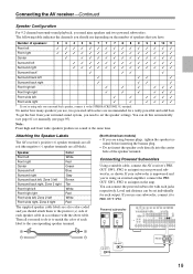
...Settings Speaker Impedance Speakers Type(FrontA) Speakers Type(FrontB) Powered Zone2 Powered Zone3 8ohms Normal BTL Not Act Not Act 2-2. Connecting the AV receiver Connecting Your Speakers About Speakers A and Speakers B Speakers A and Speakers B allows you can use the same subwoofer, center, surround...Configuration Subwoofer Front Center Surround Surr Back Use Use Use Use Not Use Speaker A 2-2. When bridging or bi-amping is used , the AV receiver can be bi-amped or bridged at a time. Two typical applications are configured by the Speakers A and Speakers B configurations means you...
...Settings Speaker Impedance Speakers Type(FrontA) Speakers Type(FrontB) Powered Zone2 Powered Zone3 8ohms Normal BTL Not Act Not Act 2-2. Connecting the AV receiver Connecting Your Speakers About Speakers A and Speakers B Speakers A and Speakers B allows you can use the same subwoofer, center, surround...Configuration Subwoofer Front Center Surround Surr Back Use Use Use Use Not Use Speaker A 2-2. When bridging or bi-amping is used , the AV receiver can be bi-amped or bridged at a time. Two typical applications are configured by the Speakers A and Speakers B configurations means you...
Owner Manual
Page 19
.... No matter how many speakers you need to set individually for a really powerful and solid bass. Attaching the Speaker Labels The AV receiver's positive (+) speaker terminals are all red (the negative (-) speaker terminals are recommended for each speaker cable in accordance with each ... Note: Front high and front wide speakers produce no sound at the same time. If your powered subwoofer, as shown. Connecting the AV receiver-Continued Speaker Configuration For 9.2-channel surround-sound playback, you 're using only one subwoofer, connect it to the SURR BACK/ZONE 3...
.... No matter how many speakers you need to set individually for a really powerful and solid bass. Attaching the Speaker Labels The AV receiver's positive (+) speaker terminals are all red (the negative (-) speaker terminals are recommended for each speaker cable in accordance with each ... Note: Front high and front wide speakers produce no sound at the same time. If your powered subwoofer, as shown. Connecting the AV receiver-Continued Speaker Configuration For 9.2-channel surround-sound playback, you 're using only one subwoofer, connect it to the SURR BACK/ZONE 3...
Owner Manual
Page 20
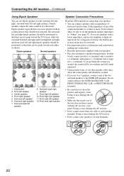
...terminal. Surround right speaker 7. If you get them to several terminals. 20 Dipole speakers output the same sound in protection circuit may damage the AV receiver. • Don't connect more , but less than one speaker to indicate how they should be avoided. • If you use speakers ...or more than 6 ohms, be out of phase and will sound unnatural. • Unnecessarily long, or very thin speaker cables may damage the AV receiver. • Don't connect one cable to the SURR L/R terminals. Dipole speakers typically have contact with an impedance of between 4 and 16 ohms....
...terminal. Surround right speaker 7. If you get them to several terminals. 20 Dipole speakers output the same sound in protection circuit may damage the AV receiver. • Don't connect more , but less than one speaker to indicate how they should be avoided. • If you use speakers ...or more than 6 ohms, be out of phase and will sound unnatural. • Unnecessarily long, or very thin speaker cables may damage the AV receiver. • Don't connect one cable to the SURR L/R terminals. Dipole speakers typically have contact with an impedance of between 4 and 16 ohms....

Owner Manual
Page 21
... left speaker Front high left speaker Center speaker Surround right speaker Surround back right speaker Surround back left speaker Surround left speaker 21 Connecting the AV receiver-Continued Connecting the Speaker Cables 1 Strip 1/2" to 5/8" (12 to 15 mm) of insulation from the ends of terminals. If you're using only one surround...
... left speaker Front high left speaker Center speaker Surround right speaker Surround back right speaker Surround back left speaker Surround left speaker 21 Connecting the AV receiver-Continued Connecting the Speaker Cables 1 Strip 1/2" to 5/8" (12 to 15 mm) of insulation from the ends of terminals. If you're using only one surround...
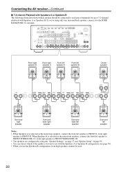
Owner Manual
Page 22
... using the "Speaker Settings" on page 57 and "Speaker Setup" on page 95. • You can choose which speaker should be used. 22 Connecting the AV receiver-Continued ■ 7.2-channel Playback with Speakers A or Speakers B The following illustration shows which of terminals for up to 7.2-channel playback with Speakers A or Speakers...
... using the "Speaker Settings" on page 57 and "Speaker Setup" on page 95. • You can choose which speaker should be used. 22 Connecting the AV receiver-Continued ■ 7.2-channel Playback with Speakers A or Speakers B The following illustration shows which of terminals for up to 7.2-channel playback with Speakers A or Speakers...
Owner Manual
Page 23
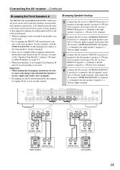
...speakers that link the Speakers' tweeter (high) and woofer (low) terminals. • Bi-amping can - nect to your speaker manual. And connect the AV receiver's SURR BACK/ZONE 3 L negative (-) terminal to the left speaker's positive (+) Woofer (low) terminal. not be wired normally or not used . &#... terminal posts connect to the front speakers' tweeter terminals. • Once you've completed the bi-amping connections shown below and turned on the AV receiver, you must set the "Speakers Type(FrontA)" setting to "Bi-Amp" to the right speaker's positive (+) Woofer (low) terminal. Bi-amping...
...speakers that link the Speakers' tweeter (high) and woofer (low) terminals. • Bi-amping can - nect to your speaker manual. And connect the AV receiver's SURR BACK/ZONE 3 L negative (-) terminal to the left speaker's positive (+) Woofer (low) terminal. not be wired normally or not used . &#... terminal posts connect to the front speakers' tweeter terminals. • Once you've completed the bi-amping connections shown below and turned on the AV receiver, you must set the "Speakers Type(FrontA)" setting to "Bi-Amp" to the right speaker's positive (+) Woofer (low) terminal. Bi-amping...


