Owner Manual
Page 1
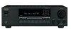
Others Troubleshooting 31 Specifications 33 En Following the instructions in the unit. Please retain this manual will enable you for future reference. Please read this manual thoroughly before making connections and plugging in this manual for purchasing an Onkyo Stereo Receiver. Stereo Receiver TX-8255 Instruction Manual Contents Introduction 2 Connections 12 Enjoying Audio Sources 19 Thank you to obtain optimum performance and listening enjoyment from your new Stereo Receiver.
Others Troubleshooting 31 Specifications 33 En Following the instructions in the unit. Please retain this manual will enable you for future reference. Please read this manual thoroughly before making connections and plugging in this manual for purchasing an Onkyo Stereo Receiver. Stereo Receiver TX-8255 Instruction Manual Contents Introduction 2 Connections 12 Enjoying Audio Sources 19 Thank you to obtain optimum performance and listening enjoyment from your new Stereo Receiver.
Owner Manual
Page 3
...of mild detergent and water. If you do not use it on the unit, contact your Onkyo dealer. 3. Handling Notes • If you need to radio or television reception, which the receiver is set to the correct voltage for a long time, it may cause harmful interference to ... liquid gets inside the unit is illegal without the permission of the following measures: • Reorient or relocate the receiving antenna. • Increase the separation between the equipment and receiver. • Connect the equipment into an outlet on the case. • This unit's top and rear panels ...
...of mild detergent and water. If you do not use it on the unit, contact your Onkyo dealer. 3. Handling Notes • If you need to radio or television reception, which the receiver is set to the correct voltage for a long time, it may cause harmful interference to ... liquid gets inside the unit is illegal without the permission of the following measures: • Reorient or relocate the receiving antenna. • Increase the separation between the equipment and receiver. • Connect the equipment into an outlet on the case. • This unit's top and rear panels ...
Owner Manual
Page 4
... L or coloured red. If the fuse needs to be replaced, the replacement fuse must approved by ASTA or BSI to Know the Receiver 6 Front Panel 6 Rear Panel 8 Display 9 Remote Controller 10 Using the Remote Controller 11 Connections Connecting Your Speakers 12 Speaker Connection...other than European model 29 Entering a Name 29 Correcting a Character 29 Connecting Components not Reached by qualified service personnel. MIYAGI ONKYO EUROPE ELECTRONICS GmbH 4 Table of Contents Introduction Important Safety Instructions 2 Precautions 3 Table of the fuse. If the power cord's plug is...
... L or coloured red. If the fuse needs to be replaced, the replacement fuse must approved by ASTA or BSI to Know the Receiver 6 Front Panel 6 Rear Panel 8 Display 9 Remote Controller 10 Using the Remote Controller 11 Connections Connecting Your Speakers 12 Speaker Connection...other than European model 29 Entering a Name 29 Correcting a Character 29 Connecting Components not Reached by qualified service personnel. MIYAGI ONKYO EUROPE ELECTRONICS GmbH 4 Table of Contents Introduction Important Safety Instructions 2 Precautions 3 Table of the fuse. If the power cord's plug is...

Owner Manual
Page 6
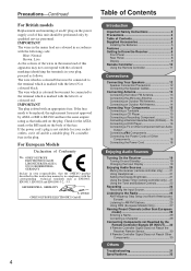
Getting to Know the Receiver Front Panel North American Model 12 34 5 67 8 9 J R Q P O NM L K Other Models 12 * The name of the buttons and other controls varies according to the description on the next page. 34 5 67 8 9 J R Q P O NM L K 6 For details, refer to the shipping destination.
Getting to Know the Receiver Front Panel North American Model 12 34 5 67 8 9 J R Q P O NM L K Other Models 12 * The name of the buttons and other controls varies according to the description on the next page. 34 5 67 8 9 J R Q P O NM L K 6 For details, refer to the shipping destination.
Owner Manual
Page 7
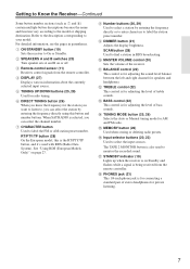
... the sound level balance between the left and right channel for adjusting the level of bass sounds. A ON/STANDBY button (19) Sets the receiver to your model. D DISPLAY (27) Displays various information about the currently selected input source. H Number buttons (26, 29) Used to...MODE button (25, 26) Selects the Auto or Manual tuning mode for private listening. 7 When SAT RADIO is for connecting a standard pair of the receiver. I DIMMER button (21) Adjusts the display brightness. SCAN button (28) Used to monitor the recorded sound. G CHARACTER button Used to select the ...
... the sound level balance between the left and right channel for adjusting the level of bass sounds. A ON/STANDBY button (19) Sets the receiver to your model. D DISPLAY (27) Displays various information about the currently selected input source. H Number buttons (26, 29) Used to...MODE button (25, 26) Selects the Auto or Manual tuning mode for private listening. 7 When SAT RADIO is for connecting a standard pair of the receiver. I DIMMER button (21) Adjusts the display brightness. SCAN button (28) Used to monitor the recorded sound. G CHARACTER button Used to select the ...
Owner Manual
Page 8
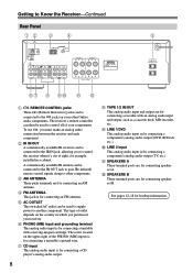
...used to supply power to another component. See pages 12-18 for example, installed in which you must make an analog audio connection between the receiver and each component. E AC OUTLET This switched AC outlet can be used to control all of the PHONO (MM) inputs is for connecting ...the IR IN jack, allowing you to control the receiver when it's out of outlet depends on the country in a cabinet. A commercially available IR emitter can be connected to the IR OUT jack to pass IR (infrared) remote control signals along to other Onkyo audio components. J LINE 2 input This analog ...
...used to supply power to another component. See pages 12-18 for example, installed in which you must make an analog audio connection between the receiver and each component. E AC OUTLET This switched AC outlet can be used to control all of the PHONO (MM) inputs is for connecting ...the IR IN jack, allowing you to control the receiver when it's out of outlet depends on the country in a cabinet. A commercially available IR emitter can be connected to the IR OUT jack to pass IR (infrared) remote control signals along to other Onkyo audio components. J LINE 2 input This analog ...

Owner Manual
Page 9
... various information about the selected input source. 9 Indicator B lights up when speaker set B is on. 2 MUTING indicator Flashes while the receiver is on. RDS (European models only): Lights up when Auto Tuning is selected, and disappears when Manual Tuning mode is selected. Getting to... Know the Receiver-Continued Display 12 3 4 5 For detailed information, see the pages in parentheses. 1 A and B speaker indicators Indicator A lights up when speaker ...
... various information about the selected input source. 9 Indicator B lights up when speaker set B is on. 2 MUTING indicator Flashes while the receiver is on. RDS (European models only): Lights up when Auto Tuning is selected, and disappears when Manual Tuning mode is selected. Getting to... Know the Receiver-Continued Display 12 3 4 5 For detailed information, see the pages in parentheses. 1 A and B speaker indicators Indicator A lights up when speaker ...

Owner Manual
Page 10
Remote Controller For detailed information, see the pages in parentheses. 1 7 2 8 9 3 J 4 5 K L M N O P Q 6 R A STANDBY/ON button (19) Sets the receiver to enter the station frequency directly or cancel the number entry. B SLEEP button (21) Used with the repeat playback functions. D CLR button (25) Used to ...
Remote Controller For detailed information, see the pages in parentheses. 1 7 2 8 9 3 J 4 5 K L M N O P Q 6 R A STANDBY/ON button (19) Sets the receiver to enter the station frequency directly or cancel the number entry. B SLEEP button (21) Used with the repeat playback functions. D CLR button (25) Used to ...

Owner Manual
Page 11
... and fast forward. Stop [ ]: Stops playback on an HDD component. Stop [ ]: Stops playback. The remote controller will not work reliably if the receiver is installed in a rack behind colored glass doors. Pressing them repeatedly selects earlier or later tracks. P DECK B buttons On twin cassette decks, only ...deck B can be pressed inadvertently, thereby draining the batteries. • The remote controller may not work reliably if the receiver is subjected to equipment that uses infrared rays, the remote controller may be controlled. Keep this in the same room, or the...
... and fast forward. Stop [ ]: Stops playback on an HDD component. Stop [ ]: Stops playback. The remote controller will not work reliably if the receiver is installed in a rack behind colored glass doors. Pressing them repeatedly selects earlier or later tracks. P DECK B buttons On twin cassette decks, only ...deck B can be pressed inadvertently, thereby draining the batteries. • The remote controller may not work reliably if the receiver is subjected to equipment that uses infrared rays, the remote controller may be controlled. Keep this in the same room, or the...
Owner Manual
Page 12
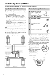
...posts, or when you make an incorrect setting for the speakers or the impedance values, the built-in protection circuit may damage the receiver. • Don't connect more than one set , use both speaker terminal posts and output sound only from speakers. Doing so may... unnatural. • Unnecessarily long or very thin speaker cables may damage the receiver. • Don't connect a speaker to each speaker terminal. The following illustration shows which speaker set A Left speaker -+ -+ Receiver Connecting the Speaker Cables 1 Strip about 15 mm (5/8 inch) of insulation from...
...posts, or when you make an incorrect setting for the speakers or the impedance values, the built-in protection circuit may damage the receiver. • Don't connect more than one set , use both speaker terminal posts and output sound only from speakers. Doing so may... unnatural. • Unnecessarily long or very thin speaker cables may damage the receiver. • Don't connect a speaker to each speaker terminal. The following illustration shows which speaker set A Left speaker -+ -+ Receiver Connecting the Speaker Cables 1 Strip about 15 mm (5/8 inch) of insulation from...
Owner Manual
Page 13
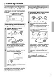
...into an AM radio station and adjust the position of the AM loop antenna to connect commercially available outdoor FM and AM antennas. Once your receiver is ready for use the tuner. If you 'll need to use , you cannot achieve good reception with a commercially available outdoor AM antenna... (see page 14). 13 The receiver won't pick up any radio signals without any antenna connected, so you must connect the antenna to tune into the base, as shown. Once ...
...into an AM radio station and adjust the position of the AM loop antenna to connect commercially available outdoor FM and AM antennas. Once your receiver is ready for use the tuner. If you 'll need to use , you cannot achieve good reception with a commercially available outdoor AM antenna... (see page 14). 13 The receiver won't pick up any radio signals without any antenna connected, so you must connect the antenna to tune into the base, as shown. Once ...

Owner Manual
Page 14
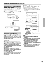
...; For safety reasons, outdoor antenna should be used in accordance with local regulations to the loop antenna, as shown. TV/FM antenna splitter To the receiver To TV (or VCR) 14 Outdoor antenna must be grounded in addition to prevent electrical shock hazards.
...; For safety reasons, outdoor antenna should be used in accordance with local regulations to the loop antenna, as shown. TV/FM antenna splitter To the receiver To TV (or VCR) 14 Outdoor antenna must be grounded in addition to prevent electrical shock hazards.
Owner Manual
Page 15
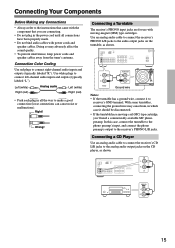
... • If the turntable has a moving -magnet (MM) type cartridges. Connecting a CD Player Use an analog audio cable to connect the receiver's CD L/R jacks to the analog audio output jacks on the turntable, as shown. ANALOG OUT 15 Doing so may cause hum, in which case... phono preamp's input, and connect the phono preamp's output to connect left-channel audio inputs and outputs (typically labeled "L"). Connecting a Turntable The receiver's PHONO input jacks are connecting. • Do not plug in all connections have been properly made. • Do not bind audio cables with...
... • If the turntable has a moving -magnet (MM) type cartridges. Connecting a CD Player Use an analog audio cable to connect the receiver's CD L/R jacks to the analog audio output jacks on the turntable, as shown. ANALOG OUT 15 Doing so may cause hum, in which case... phono preamp's input, and connect the phono preamp's output to connect left-channel audio inputs and outputs (typically labeled "L"). Connecting a Turntable The receiver's PHONO input jacks are connecting. • Do not plug in all connections have been properly made. • Do not bind audio cables with...
Owner Manual
Page 16
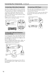
... Dock (RI Dock) Use an analog audio cable to connect the TAPE 1 IN L/R jacks to "HDD," you want to monitor the recorded sound, use the Onkyo Remote Interactive Dock (DS-A1), flip the RI MODE switch to the analog audio output jacks on the underside. 16 The video input from... the DVD player can operate the RI Dock using the remote controller supplied with the receiver (see page 19). When you use the TAPE 2 jacks for connecting a recorder. L AUDIO OUT Note: If you change the input display name to the RI...
... Dock (RI Dock) Use an analog audio cable to connect the TAPE 1 IN L/R jacks to "HDD," you want to monitor the recorded sound, use the Onkyo Remote Interactive Dock (DS-A1), flip the RI MODE switch to the analog audio output jacks on the underside. 16 The video input from... the DVD player can operate the RI Dock using the remote controller supplied with the receiver (see page 19). When you use the TAPE 2 jacks for connecting a recorder. L AUDIO OUT Note: If you change the input display name to the RI...
Owner Manual
Page 17
... on an audio component connected via , the receiver will automatically select that 's connected to the receiver, the receiver will go on with the receiver's remote controller. • To use with Onkyo products (no cables are supplied with the receiver). • jacks should be connected only to.... Remote control cable Notes: • Push each audio component. Connecting them to another manufacturer's component may cause the receiver to work). connector Onkyo cassette deck, etc. See pages 10-11 for this to malfunction. • Some components may not support all components...
... on an audio component connected via , the receiver will automatically select that 's connected to the receiver, the receiver will go on with the receiver's remote controller. • To use with Onkyo products (no cables are supplied with the receiver). • jacks should be connected only to.... Remote control cable Notes: • Push each audio component. Connecting them to another manufacturer's component may cause the receiver to work). connector Onkyo cassette deck, etc. See pages 10-11 for this to malfunction. • Some components may not support all components...
Owner Manual
Page 18
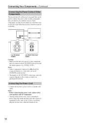
... model Caution: • Make sure that the total capacity of the components that you connect to a wall outlet, not an AC OUTLETS on the receiver. • The number of AC OUTLETS, socket type, and total capacity depends on the country in which you intend to a suitable wall outlet. Notes:... • Onkyo components connected via should be connected directly to the AC OUTLETS does not exceed the stated capacity (e.g., TOTAL 120 W). If this is turned on and...
... model Caution: • Make sure that the total capacity of the components that you connect to a wall outlet, not an AC OUTLETS on the receiver. • The number of AC OUTLETS, socket type, and total capacity depends on the country in which you intend to a suitable wall outlet. Notes:... • Onkyo components connected via should be connected directly to the AC OUTLETS does not exceed the stated capacity (e.g., TOTAL 120 W). If this is turned on and...

Owner Manual
Page 19
... Remote controller Press the [ON/STANDBY] button. Changing the Input Display You can operate the RI Dock using the remote controller supplied with the receiver (see pages 10-11). 1 Press the appropriate input selector button. The selected input name appears in the display. 2 Press and hold down the ...volume before you can change the input display name to change the display name. 19 The receiver will enter Standby mode. When the input display name has been changed "HDD" for TAPE 1, the display name for the other button cannot be...
... Remote controller Press the [ON/STANDBY] button. Changing the Input Display You can operate the RI Dock using the remote controller supplied with the receiver (see pages 10-11). 1 Press the appropriate input selector button. The selected input name appears in the display. 2 Press and hold down the ...volume before you can change the input display name to change the display name. 19 The receiver will enter Standby mode. When the input display name has been changed "HDD" for TAPE 1, the display name for the other button cannot be...
Owner Manual
Page 20
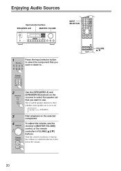
... adjust the volume, use . Turn the control clockwise to turn down the volume. Indicators 3 4 Receiver Remote controller Start playback on or off. VOLUME / 20 Remote controller 2 Receiver Use the [SPEAKERS A] and [SPEAKERS B] buttons on the receiver to use the receiver's [MASTER VOLUME] control, or the remote controller's VOLUME [ ]/[ ] buttons. Enjoying Audio Sources Input selector...
... adjust the volume, use . Turn the control clockwise to turn down the volume. Indicators 3 4 Receiver Remote controller Start playback on or off. VOLUME / 20 Remote controller 2 Receiver Use the [SPEAKERS A] and [SPEAKERS B] buttons on the receiver to use the receiver's [MASTER VOLUME] control, or the remote controller's VOLUME [ ]/[ ] buttons. Enjoying Audio Sources Input selector...
Owner Manual
Page 21
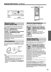
...A and SPEAKERS B buttons. Using the Sleep Timer (remote controller only) With the sleep timer, you can temporarily mute the output of the receiver. 1 Press the remote controller's [MUTING] button. You can adjust the brightness of stereo headphones (1/4-inch phone plug) to select: dim, dimmer..., or normal brightness. Note: The Mute function will be cancelled if the remote controller's VOLUME buttons are pressed or the receiver is inserted in 10 minute steps. Setting the Display Brightness You can set , as shown. Alternatively, you can connect a pair of the...
...A and SPEAKERS B buttons. Using the Sleep Timer (remote controller only) With the sleep timer, you can temporarily mute the output of the receiver. 1 Press the remote controller's [MUTING] button. You can adjust the brightness of stereo headphones (1/4-inch phone plug) to select: dim, dimmer..., or normal brightness. Note: The Mute function will be cancelled if the remote controller's VOLUME buttons are pressed or the receiver is inserted in 10 minute steps. Setting the Display Brightness You can set , as shown. Alternatively, you can connect a pair of the...

Owner Manual
Page 24
... before or after recording. Then you will see a sign "> T-2 ON" next to compare the sounds by switching the output between the sound before recording Receiver TAPE 2 T2 MONITOR OFF button Amplifier 24 PLAY REC Input source (CD, FM, etc.) However, only ">" is displayed if a tuner is... displayed, and release it when the sign changes to deactivate the sound monitoring function. The signal flow in monitoring the recorded sound Receiver TAPE 2 T2 MONITOR OFF button Amplifier T2 MONITOR ON PLAY REC TAPE 2 Input source (CD, FM, etc.) The signal fl...
... before or after recording. Then you will see a sign "> T-2 ON" next to compare the sounds by switching the output between the sound before recording Receiver TAPE 2 T2 MONITOR OFF button Amplifier 24 PLAY REC Input source (CD, FM, etc.) However, only ">" is displayed if a tuner is... displayed, and release it when the sign changes to deactivate the sound monitoring function. The signal flow in monitoring the recorded sound Receiver TAPE 2 T2 MONITOR OFF button Amplifier T2 MONITOR ON PLAY REC TAPE 2 Input source (CD, FM, etc.) The signal fl...


