

User Manual
Page 1
Save this equipment. c/o HI Group PLC, Express Way Whitwood, West Yorkshire WF10 5QJ UK CAUTION Read all precautions and instructions in the space above for future reference. Serial Number Decal QUESTIONS? Write the serial number in this manual before using this manual for reference. If you have questions, or if there are missing parts, please contact us: Call: 08457 089 009 From Ireland: 053 92 36102 E-mail: www.iconsupport.eu Write: ICON Health & Fitness, Ltd. NETL15708.0 Serial No. Model No. USER'S MANUAL www.iconeurope.com
Save this equipment. c/o HI Group PLC, Express Way Whitwood, West Yorkshire WF10 5QJ UK CAUTION Read all precautions and instructions in the space above for future reference. Serial Number Decal QUESTIONS? Write the serial number in this manual before using this manual for reference. If you have questions, or if there are missing parts, please contact us: Call: 08457 089 009 From Ireland: 053 92 36102 E-mail: www.iconsupport.eu Write: ICON Health & Fitness, Ltd. NETL15708.0 Serial No. Model No. USER'S MANUAL www.iconeurope.com
User Manual
Page 2
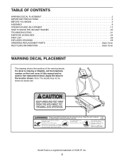
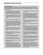
NordicTrack is missing or illegible, call the telephone number on the front cover of ICON IP, Inc. 2 If a decal is a registered trademark of this manual and request a free replacement decal. Apply the decal in the location shown. Note: The decals may not be shown at... actual size. TABLE OF CONTENTS WARNING DECAL PLACEMENT 2 IMPORTANT PRECAUTIONS 3 BEFORE YOU BEGIN 5 ASSEMBLY 6 OPERATION AND ADJUSTMENT 12 HOW TO MOVE THE INCLINE TRAINER 20 ...
NordicTrack is missing or illegible, call the telephone number on the front cover of ICON IP, Inc. 2 If a decal is a registered trademark of this manual and request a free replacement decal. Apply the decal in the location shown. Note: The decals may not be shown at... actual size. TABLE OF CONTENTS WARNING DECAL PLACEMENT 2 IMPORTANT PRECAUTIONS 3 BEFORE YOU BEGIN 5 ASSEMBLY 6 OPERATION AND ADJUSTMENT 12 HOW TO MOVE THE INCLINE TRAINER 20 ...
User Manual
Page 3
... one person on a level surface, with bare feet, wearing only stockings, or in speed. 10. Do not put the incline trainer in the incline trainer. Never move the walking belt while the power is being administered. 7. When replacing the fuse, an ASTA approved BS1362 type should...115 kg) or less. 9. Do not place the incline trainer on your physician. Keep the incline trainer indoors, away from the incline trainer at a time. 15. trainer with at least 8 ft. (2.4 m) of serious injury, read all important precautions and in this manual and all users of this or any surface that ...
... one person on a level surface, with bare feet, wearing only stockings, or in speed. 10. Do not put the incline trainer in the incline trainer. Never move the walking belt while the power is being administered. 7. When replacing the fuse, an ASTA approved BS1362 type should...115 kg) or less. 9. Do not place the incline trainer on your physician. Keep the incline trainer indoors, away from the incline trainer at a time. 15. trainer with at least 8 ft. (2.4 m) of serious injury, read all important precautions and in this manual and all users of this or any surface that ...
User Manual
Page 4
...performed by placing objects under the incline trainer. 22. Over exercising may result in this manual should be able to safely lift 45 lbs. (20 kg) to the "off" position when the incline trainer is running. 19. Never leave the incline trainer unattended while it is intended for ...- SAVE THESE INSTRUCTIONS 4 Never remove the motor hood unless instructed to move the incline trainer until it is not in use the incline trainer in any opening on page 5 for in this manual. Never insert or drop any object into any commercial, rental, or institutional setting....
...performed by placing objects under the incline trainer. 22. Over exercising may result in this manual should be able to safely lift 45 lbs. (20 kg) to the "off" position when the incline trainer is running. 19. Never leave the incline trainer unattended while it is intended for ...- SAVE THESE INSTRUCTIONS 4 Never remove the motor hood unless instructed to move the incline trainer until it is not in use the incline trainer in any opening on page 5 for in this manual. Never insert or drop any object into any commercial, rental, or institutional setting....
User Manual
Page 5
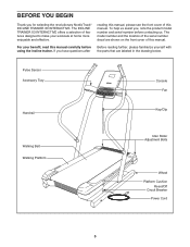
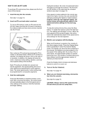
... Roller Adjustment Bolts Wheel Platform Cushion Reset/Off Circuit Breaker Power Cord 5 The model number and the location of this manual carefully before contacting us assist you for selecting the revolutionary NordicTrack® INCLINE TRAINER X3 INTERACTIVE. Before reading further, please familiarize yourself with the parts that are shown on the front cover of features...
... Roller Adjustment Bolts Wheel Platform Cushion Reset/Off Circuit Breaker Power Cord 5 The model number and the location of this manual carefully before contacting us assist you for selecting the revolutionary NordicTrack® INCLINE TRAINER X3 INTERACTIVE. Before reading further, please familiarize yourself with the parts that are shown on the front cover of features...
User Manual
Page 6
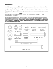
... top of the walking belt, simply wipe off the lubricant with high-performance lubricant. The number after the parentheses is normal and does not affect incline trainer performance. To avoid damaging plastic parts, do not use power tools for assembly. Extra hardware may be included. 3/8" Star Washer (9)-6 3/8" Nut (8)-2 #8 x 1/2" Screw...belt or the shipping carton. Set the incline trainer in the hardware kit, check to the top of this manual. Do not dispose of the parts to identify the assembly hardware. Note: The underside of the incline trainer walking belt is preattached to one of...
... top of the walking belt, simply wipe off the lubricant with high-performance lubricant. The number after the parentheses is normal and does not affect incline trainer performance. To avoid damaging plastic parts, do not use power tools for assembly. Extra hardware may be included. 3/8" Star Washer (9)-6 3/8" Nut (8)-2 #8 x 1/2" Screw...belt or the shipping carton. Set the incline trainer in the hardware kit, check to the top of this manual. Do not dispose of the parts to identify the assembly hardware. Note: The underside of the incline trainer walking belt is preattached to one of...
User Manual
Page 13
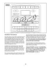
CONSOLE DIAGRAM FEATURES OF THE CONSOLE The incline trainer console offers an impressive array of this manual. To use the information mode, see the front cover of features designed to make your workouts more effective and enjoyable.... will display continuous exercise feedback. iFit workouts automatically control the incline trainer while the voice of a personal trainer coaches you through every step of a button. When the manual mode of the console is selected, the speed and incline of the incline trainer can even measure your workout. cept iFit interactive workout cards ...
CONSOLE DIAGRAM FEATURES OF THE CONSOLE The incline trainer console offers an impressive array of this manual. To use the information mode, see the front cover of features designed to make your workouts more effective and enjoyable.... will display continuous exercise feedback. iFit workouts automatically control the incline trainer while the voice of a personal trainer coaches you through every step of a button. When the manual mode of the console is selected, the speed and incline of the incline trainer can even measure your workout. cept iFit interactive workout cards ...
User Manual
Page 14
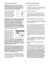
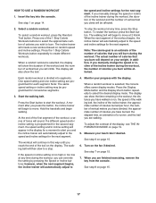
...will change the speed of the walking belt as desired by 0.1 Km/H; HOW TO TURN ON THE POWER HOW TO USE THE MANUAL MODE IMPORTANT: If the incline trainer has been exposed to cold temperatures, allow it to warm to room temperature before turning on the face of the console, remove ... the console. Reset 2. Start the walking belt and adjust the speed. When the incline is turned on. and when the incline is used if the incline trainer is inserted, the manual mode will begin to move at - Select the manual mode. If you plug in the display. If the displays light as soon as...
...will change the speed of the walking belt as desired by 0.1 Km/H; HOW TO TURN ON THE POWER HOW TO USE THE MANUAL MODE IMPORTANT: If the incline trainer has been exposed to cold temperatures, allow it to warm to room temperature before turning on the face of the console, remove ... the console. Reset 2. Start the walking belt and adjust the speed. When the incline is turned on. and when the incline is used if the incline trainer is inserted, the manual mode will begin to move at - Select the manual mode. If you plug in the display. If the displays light as soon as...
User Manual
Page 15
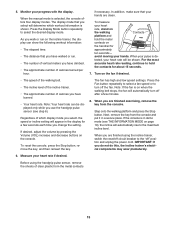
... handgrip pulse sensor (see THE INFORMATION MODE on the fan if desired. • The speed of the walking belt. • The incline level of the incline trainer. • The approximate number of calories burned per hour. When you have burned. • Your heart rate. When you select,... the console, press the Stop button, remove the key, and then reinsert the key. Monitor your heart rate if desired. When the manual mode is de- Regardless of vertical meters you have climbed. • The approximate number of calories you are finished exercising, remove the ...
... handgrip pulse sensor (see THE INFORMATION MODE on the fan if desired. • The speed of the walking belt. • The incline level of the incline trainer. • The approximate number of calories burned per hour. When you have burned. • Your heart rate. When you select,... the console, press the Stop button, remove the key, and then reinsert the key. Monitor your heart rate if desired. When the manual mode is de- Regardless of vertical meters you have climbed. • The approximate number of calories you are finished exercising, remove the ...
User Manual
Page 16
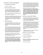
...; When you have climbed. To select a 1 step calorie workout, press the desired 1 Step Calorie Workouts button until you manually change the speed or incline of the incline trainer during the workout, you will depend on your progress. Hold the handrails and begin to a stop the workout at 2 Km...19. 5. Press the Start button to select the desired display mode. A moment after you press the button, the incline trainer will automatically adjust to the speed and incline settings for a moment to alert you burn will then slow to move . The circle above the trail will begin ...
...; When you have climbed. To select a 1 step calorie workout, press the desired 1 Step Calorie Workouts button until you manually change the speed or incline of the incline trainer during the workout, you will depend on your progress. Hold the handrails and begin to a stop the workout at 2 Km...19. 5. Press the Start button to select the desired display mode. A moment after you press the button, the incline trainer will automatically adjust to the speed and incline settings for a moment to alert you burn will then slow to move . The circle above the trail will begin ...
User Manual
Page 17
... the key into segments. See step 1 on the fan if desired. Select a random workout. The incline trainer will continue in this way until you are walking. In addition, if you manually change the speed or incline of the incline trainer during the workout, the number of tones will automatically adjust to start the workout. At the...
... the key into segments. See step 1 on the fan if desired. Select a random workout. The incline trainer will continue in this way until you are walking. In addition, if you manually change the speed or incline of the incline trainer during the workout, the number of tones will automatically adjust to start the workout. At the...
User Manual
Page 18
...2. The walking belt will guide you are inserted into the iFit slot; When the next segment of the workout begins, the incline trainer will show the name, maximum incline setting, duration, and maximum speed setting of a mountain. When an iFit workout is oriented so the metal contacts are face-... the workout, the distance you have walked or run, the speed of the walking belt, the incline of the incline trainer, the approximate number of calories burned per hour, the number of this manual. Start the walking belt. When an iFit workout is too high or too low, you have ...
...2. The walking belt will guide you are inserted into the iFit slot; When the next segment of the workout begins, the incline trainer will show the name, maximum incline setting, duration, and maximum speed setting of a mountain. When an iFit workout is oriented so the metal contacts are face-... the workout, the distance you have walked or run, the speed of the walking belt, the incline of the incline trainer, the approximate number of calories burned per hour, the number of this manual. Start the walking belt. When an iFit workout is too high or too low, you have ...
User Manual
Page 21
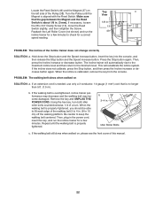
... lit when you remove the key from the console SOLUTION: a. Then, remove the three indicated #8 a x 1/2" Screws (12). b. c. If the incline trainer still will not run, please see the front cover of the console do not function properly SOLUTION: a. To turn off the Left Roller Cover (35... displays of this manual. b. Make sure that is turned on page 19 to the maximum level, the demo mode is no longer than 5 ft. (1.5 m). PROBLEM: The console displays remain lit when you remove the key and the incline rises to turn on the incline trainer frame near the power...
... lit when you remove the key from the console SOLUTION: a. Then, remove the three indicated #8 a x 1/2" Screws (12). b. c. If the incline trainer still will not run, please see the front cover of the console do not function properly SOLUTION: a. To turn off the Left Roller Cover (35... displays of this manual. b. Make sure that is turned on page 19 to the maximum level, the demo mode is no longer than 5 ft. (1.5 m). PROBLEM: The console displays remain lit when you remove the key and the incline rises to turn on the incline trainer frame near the power...
User Manual
Page 22
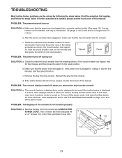
... the front cover of a turn. Remove the key and UNPLUG THE POWER CORD. Reattach the Left Roller Cover (not shown) and run the incline trainer for a correct speed reading. Press the Stop button again. Make sure Top View that is calibrated, remove the key from the console. Locate... not calibrate, press the Stop button, and then press the Incline increase or decrease button again. Using the hex key, turn both idler roller bolts counterclockwise, 1/4 of this manual. 22 Be careful to 4 in . Repeat until the Magnet is properly tightened, you should be able to lift...
... the front cover of a turn. Remove the key and UNPLUG THE POWER CORD. Reattach the Left Roller Cover (not shown) and run the incline trainer for a correct speed reading. Press the Stop button again. Make sure Top View that is calibrated, remove the key from the console. Locate... not calibrate, press the Stop button, and then press the Incline increase or decrease button again. Using the hex key, turn both idler roller bolts counterclockwise, 1/4 of this manual. 22 Be careful to 4 in . Repeat until the Magnet is properly tightened, you should be able to lift...
User Manual
Page 26
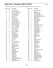
Key No. NETL15708.0 R0410A To locate the parts listed below, see the EXPLODED DRAWING near the end of this manual. Qty. 51 1 52 1 53 1 54 1 55 1 56 1 57 1 58 1 59 1 60 1 61 4 62 1 63 1 64 1 65 1 66 4 67 4 68 2 69 1 70 1 71 1 72 1 73 1 74 1 ... 1 94 1 95 1 96 1 97 1 98 2 99 8 100 3 Description Left Rear Cushion Frame Belly Pan Plate Front Left Cushion Front Belly Pan Top Incline Motor Cover Bottom Incline Motor Cover Incline Motor Wire Clamp Electronics Plate Plastic Standoff PCB Board Controller Drive Motor Resistance Mechanism Pulse Plate Pulse Plate Housing Pulse Handle Left Handrail...
Key No. NETL15708.0 R0410A To locate the parts listed below, see the EXPLODED DRAWING near the end of this manual. Qty. 51 1 52 1 53 1 54 1 55 1 56 1 57 1 58 1 59 1 60 1 61 4 62 1 63 1 64 1 65 1 66 4 67 4 68 2 69 1 70 1 71 1 72 1 73 1 74 1 ... 1 94 1 95 1 96 1 97 1 98 2 99 8 100 3 Description Left Rear Cushion Frame Belly Pan Plate Front Left Cushion Front Belly Pan Top Incline Motor Cover Bottom Incline Motor Cover Incline Motor Wire Clamp Electronics Plate Plastic Standoff PCB Board Controller Drive Motor Resistance Mechanism Pulse Plate Pulse Plate Housing Pulse Handle Left Handrail...

User Manual
Page 27
Qty. 101 1 102 1 103 1 104 1 105 1 106 1 Description Shield Warning Decal Motor Shield Audio Wire Incline Sensor Wire Transformer Filter Key No. Description Power Cord Adapter Drive Motor Plate Drive Motor Isolator Rubber Washer 5/16" Flat Washer Userʼs Manual Note: Specifications are not illustrated. 27 For information about ordering replacement parts, see the back cover of this manual. *These parts are subject to change without notice. Key No. Qty. 107 1 108 1 109 2 110 4 111 2 * -
Qty. 101 1 102 1 103 1 104 1 105 1 106 1 Description Shield Warning Decal Motor Shield Audio Wire Incline Sensor Wire Transformer Filter Key No. Description Power Cord Adapter Drive Motor Plate Drive Motor Isolator Rubber Washer 5/16" Flat Washer Userʼs Manual Note: Specifications are not illustrated. 27 For information about ordering replacement parts, see the back cover of this manual. *These parts are subject to change without notice. Key No. Qty. 107 1 108 1 109 2 110 4 111 2 * -
User Manual
Page 32
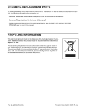
...where you , be disposed of waste in USA © 2010 ICON IP, Inc. In doing so, you will help us assist you purchased this manual) RECYCLING INFORMATION This electronic product must be recycled after its useful life as required by law. To help to provide the following information when contacting... us: • the model number and serial number of the product (see the front cover of this manual) • the name of the product (see the front cover of this manual) • the key number and description of the replacement part(s) (see the front cover of this product must...
...where you , be disposed of waste in USA © 2010 ICON IP, Inc. In doing so, you will help us assist you purchased this manual) RECYCLING INFORMATION This electronic product must be recycled after its useful life as required by law. To help to provide the following information when contacting... us: • the model number and serial number of the product (see the front cover of this manual) • the name of the product (see the front cover of this manual) • the key number and description of the replacement part(s) (see the front cover of this product must...

