

User Manual
Page 2
TABLE OF CONTENTS WARNING DECAL PLACEMENT 2 IMPORTANT PRECAUTIONS 3 BEFORE YOU BEGIN 4 ASSEMBLY 5 HOW TO USE THE ELLIPTICAL EXERCISER 13 MAINTENANCE AND TROUBLESHOOTING 21 EXERCISE GUIDELINES 23 PART LIST 24 EXPLODED DRAWING 26 ORDERING REPLACEMENT PARTS Back Cover LIMITED WARRANTY Back Cover ... of this manual and request a free replacement decal. If a decal is a registered trademark of ICON IP, Inc. 2 Apply the decal in the location shown. NordicTrack is missing or illegible, see the front cover of the warning decal(s). Note: The decal(s) may not be shown at actual size.
TABLE OF CONTENTS WARNING DECAL PLACEMENT 2 IMPORTANT PRECAUTIONS 3 BEFORE YOU BEGIN 4 ASSEMBLY 5 HOW TO USE THE ELLIPTICAL EXERCISER 13 MAINTENANCE AND TROUBLESHOOTING 21 EXERCISE GUIDELINES 23 PART LIST 24 EXPLODED DRAWING 26 ORDERING REPLACEMENT PARTS Back Cover LIMITED WARRANTY Back Cover ... of this manual and request a free replacement decal. If a decal is a registered trademark of ICON IP, Inc. 2 Apply the decal in the location shown. NordicTrack is missing or illegible, see the front cover of the warning decal(s). Note: The decal(s) may not be shown at actual size.

User Manual
Page 5
and a rubber As you assemble the elliptical exerciser, use the drawings below each drawing is the quantity needed for assembly. M8 x 16mm x 2mm M8 x 23mm x 2mm M8 x 23.5mm x 1mm Small Wave Washer (120)-2 Washer (126)-2 Washer (110)-2 Washer (118)-2 Medium Wave ...Patch Screw (121)-2 M10 x 80mm Patch Screw (100)-4 5 Place all parts of the packing materials until assembly is completed. In addition to identify small parts. Do not dispose of the elliptical exerciser in a cleared area and remove the packing materials. The number following the parentheses is the key number ...
and a rubber As you assemble the elliptical exerciser, use the drawings below each drawing is the quantity needed for assembly. M8 x 16mm x 2mm M8 x 23mm x 2mm M8 x 23.5mm x 1mm Small Wave Washer (120)-2 Washer (126)-2 Washer (110)-2 Washer (118)-2 Medium Wave ...Patch Screw (121)-2 M10 x 80mm Patch Screw (100)-4 5 Place all parts of the packing materials until assembly is completed. In addition to identify small parts. Do not dispose of the elliptical exerciser in a cleared area and remove the packing materials. The number following the parentheses is the key number ...

User Manual
Page 6
Identify and orient the Front Stabilizer (3) as shown. 2 While another person lifts the Frame (1), attach the Front Stabilizer (3) to the Folding Frame with two M10 x 80mm Patch Screws (100) and two M10 Split Washers (123). 2. While another person lifts the Folding Frame (2), attach the Rear Stabilizer (4) to the Frame with two M10 x 80mm Patch Screws (100) and two M10 Split Washers (123). 100 123 3 1 4 2 100 123 6 1. Identify and orient the Rear Stabilizer (4) as shown. To make assembly easier, read the 1 information on page 5 before you begin.
Identify and orient the Front Stabilizer (3) as shown. 2 While another person lifts the Frame (1), attach the Front Stabilizer (3) to the Folding Frame with two M10 x 80mm Patch Screws (100) and two M10 Split Washers (123). 2. While another person lifts the Folding Frame (2), attach the Rear Stabilizer (4) to the Frame with two M10 x 80mm Patch Screws (100) and two M10 Split Washers (123). 100 123 3 1 4 2 100 123 6 1. Identify and orient the Rear Stabilizer (4) as shown. To make assembly easier, read the 1 information on page 5 before you begin.

User Manual
Page 12
... the Left Rear and Front Leg Covers 6 (31, 32) in the same way. To protect the floor or carpet from damage, place a mat under the elliptical exerciser. 12 Attach the Front Upright Cover (25) around the Right Upper Body Leg (6) by pressing the tabs on the Right Front Leg Cover into... Round Head Screws (106). Tighten the four M8 x 16mm Patch Screws (102). 29 Then, slide the Top Cover (23) downward and press it over after assembly is completed. See step 3. Identify the Right Rear and Front Leg Covers (29, 30), which are properly tightened. Note: Some hardware may be left over...
... the Left Rear and Front Leg Covers 6 (31, 32) in the same way. To protect the floor or carpet from damage, place a mat under the elliptical exerciser. 12 Attach the Front Upright Cover (25) around the Right Upper Body Leg (6) by pressing the tabs on the Right Front Leg Cover into... Round Head Screws (106). Tighten the four M8 x 16mm Patch Screws (102). 29 Then, slide the Top Cover (23) downward and press it over after assembly is completed. See step 3. Identify the Right Rear and Front Leg Covers (29, 30), which are properly tightened. Note: Some hardware may be left over...

User Manual
Page 15
... continuous exercise feedback. CONSOLE DIAGRAM FEATURES OF THE CONSOLE This console offers an array of features designed to make sure that batteries are installed (see assembly step 9 on page 10). To use the manual mode of the console, you can even connect your MP3 player or CD player to the console...
... continuous exercise feedback. CONSOLE DIAGRAM FEATURES OF THE CONSOLE This console offers an array of features designed to make sure that batteries are installed (see assembly step 9 on page 10). To use the manual mode of the console, you can even connect your MP3 player or CD player to the console...
User Manual
Page 21
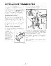
...Pulley (74) until the console displays correct feedback. Then, retighten the M4 x 16mm Screw (93). most console problems are the result of the elliptical exerciser regularly. To adjust the reed switch, you use a damp cloth and a small amount of direct sunlight. Slide the Reed Switch slightly toward or...and keep the console out of mild soap. Repeat these actions until a Magnet (75) is correctly adjusted, reattach the top shield. 21 See assembly step 9 on the front and rear of the Top Shield and then remove the Top Shield. IMPORTANT: To avoid damage to the console, ...
...Pulley (74) until the console displays correct feedback. Then, retighten the M4 x 16mm Screw (93). most console problems are the result of the elliptical exerciser regularly. To adjust the reed switch, you use a damp cloth and a small amount of direct sunlight. Slide the Reed Switch slightly toward or...and keep the console out of mild soap. Repeat these actions until a Magnet (75) is correctly adjusted, reattach the top shield. 21 See assembly step 9 on the front and rear of the Top Shield and then remove the Top Shield. IMPORTANT: To avoid damage to the console, ...

User Manual
Page 24
...92 1 93 7 94 2 95 1 96 1 97 1 98 2 99 1 100 4 R0909A Description Latch Spring Latch Insert Adjustment Arm Spring Leg Bearing Assembly Leg Spacer Axle Cover Upright Bushing Pedal Arm Bushing Audio Cable Wire Harness Flywheel 6000ZZ Bearing Frame Axle Frame Bushing Latch Bracket Axle Latch Bracket...Button Housing Reed Switch/Wire Clamp Crank Hub Crank Crank Spacer Large Pulley Magnet Folding Frame Bearing Idler Resistance Motor Adjustment Assembly Resistance Wheel Adjustment Lock Motor Bracket C-magnet Bracket Flywheel Axle Belt Adjustment Screw M8 x 28mm Patch Screw Small Snap ...
...92 1 93 7 94 2 95 1 96 1 97 1 98 2 99 1 100 4 R0909A Description Latch Spring Latch Insert Adjustment Arm Spring Leg Bearing Assembly Leg Spacer Axle Cover Upright Bushing Pedal Arm Bushing Audio Cable Wire Harness Flywheel 6000ZZ Bearing Frame Axle Frame Bushing Latch Bracket Axle Latch Bracket...Button Housing Reed Switch/Wire Clamp Crank Hub Crank Crank Spacer Large Pulley Magnet Folding Frame Bearing Idler Resistance Motor Adjustment Assembly Resistance Wheel Adjustment Lock Motor Bracket C-magnet Bracket Flywheel Axle Belt Adjustment Screw M8 x 28mm Patch Screw Small Snap ...

User Manual
Page 25
... Patch Screw 3/8" x 1" Flange Screw M10 Split Washer M4 x 42mm Screw M4 x 42mm Flat Head Screw M8 x 23mm x 2mm Washer Long C-pin Short C-pin User's Manual Assembly Tool Note: Specifications are not illustrated. 25 For information about ordering replacement parts, see the back cover of this manual. *These parts are subject to...
... Patch Screw 3/8" x 1" Flange Screw M10 Split Washer M4 x 42mm Screw M4 x 42mm Flat Head Screw M8 x 23mm x 2mm Washer Long C-pin Short C-pin User's Manual Assembly Tool Note: Specifications are not illustrated. 25 For information about ordering replacement parts, see the back cover of this manual. *These parts are subject to...


