
Hardware Manual
Page 3
... Getting Started Additional Documentation 8 Setup Location 8 Supported Operating Systems 8 Supported Browsers 9 Diskless Storage Systems 9 Chapter 2 NETGEAR ReadyNAS 102 Front and Side Panels 11 Drive Bays 12 Rear Panel 13 Status Information 14 Power On and Shut Down 15 Power On 15 Preferred Shutdown 15 Forced Shutdown ...15 Power State 15 Boot Menu 16 Chapter 3 NETGEAR ReadyNAS 104 Front and Side Panels 19 Drive Bays 20 Rear Panel 21 Status Information 22 Power On and Shut Down 23 Power On 23 Preferred Shutdown ...
... Getting Started Additional Documentation 8 Setup Location 8 Supported Operating Systems 8 Supported Browsers 9 Diskless Storage Systems 9 Chapter 2 NETGEAR ReadyNAS 102 Front and Side Panels 11 Drive Bays 12 Rear Panel 13 Status Information 14 Power On and Shut Down 15 Power On 15 Preferred Shutdown 15 Forced Shutdown ...15 Power State 15 Boot Menu 16 Chapter 3 NETGEAR ReadyNAS 104 Front and Side Panels 19 Drive Bays 20 Rear Panel 21 Status Information 22 Power On and Shut Down 23 Power On 23 Preferred Shutdown ...

Hardware Manual
Page 4
... On and Shut Down 42 Power On 42 Preferred Shutdown 42 Forced Shutdown 43 Power State 43 Boot Menu 43 Chapter 6 NETGEAR ReadyNAS 212 Front and Side Panels 46 Drive Bays 47 Rear Panel 48 Status Information 49 Power On and Shut Down 50 Power On 50 Preferred Shutdown 50 Forced Shutdown... 50 Power State 51 Boot Menu 51 Chapter 7 NETGEAR ReadyNAS 214 Front and Side Panels 56 Drive Bays 57 Rear Panel 58 Status Information 59 Power On and Shut Down 60 Power On 60 Preferred Shutdown 60 Forced Shutdown...
... On and Shut Down 42 Power On 42 Preferred Shutdown 42 Forced Shutdown 43 Power State 43 Boot Menu 43 Chapter 6 NETGEAR ReadyNAS 212 Front and Side Panels 46 Drive Bays 47 Rear Panel 48 Status Information 49 Power On and Shut Down 50 Power On 50 Preferred Shutdown 50 Forced Shutdown... 50 Power State 51 Boot Menu 51 Chapter 7 NETGEAR ReadyNAS 214 Front and Side Panels 56 Drive Bays 57 Rear Panel 58 Status Information 59 Power On and Shut Down 60 Power On 60 Preferred Shutdown 60 Forced Shutdown...

Hardware Manual
Page 5
... Information 67 Power On and Shut Down 68 Power On 68 Preferred Shutdown 68 Forced Shutdown 68 Boot Menu 69 Chapter 9 NETGEAR ReadyNAS 314 Front and Side Panels 72 Drive Bays 73 Rear Panel 74 Status Information 75 Power On and Shut Down 76 Power On 76 Preferred Shutdown 76 Forced Shutdown... 76 Boot Menu 77 Chapter 10 NETGEAR ReadyNAS 316 Front and Side Panels 80 Drive Bays 81 Rear Panel 82 Status Information 83 Power On and Shut Down 83 Power On 83 Preferred Shutdown 83 Forced Shutdown...
... Information 67 Power On and Shut Down 68 Power On 68 Preferred Shutdown 68 Forced Shutdown 68 Boot Menu 69 Chapter 9 NETGEAR ReadyNAS 314 Front and Side Panels 72 Drive Bays 73 Rear Panel 74 Status Information 75 Power On and Shut Down 76 Power On 76 Preferred Shutdown 76 Forced Shutdown... 76 Boot Menu 77 Chapter 10 NETGEAR ReadyNAS 316 Front and Side Panels 80 Drive Bays 81 Rear Panel 82 Status Information 83 Power On and Shut Down 83 Power On 83 Preferred Shutdown 83 Forced Shutdown...

Hardware Manual
Page 6
... Systems Power On and Shut Down 99 Power On 100 Preferred Shutdown 100 Forced Shutdown 100 Boot Menu 101 Chapter 13 NETGEAR EDA 500 Front and Side Panels 104 Drive Bays 105 Rear Panel 106 Status Information 107 Power On and Shut Down 108 Power On 108 Preferred Shutdown 108 Forced Shutdown...
... Systems Power On and Shut Down 99 Power On 100 Preferred Shutdown 100 Forced Shutdown 100 Boot Menu 101 Chapter 13 NETGEAR EDA 500 Front and Side Panels 104 Drive Bays 105 Rear Panel 106 Status Information 107 Power On and Shut Down 108 Power On 108 Preferred Shutdown 108 Forced Shutdown...

Hardware Manual
Page 9
... local admin page, see Add a Disk on page 112. If you are not supported, NETGEAR technical support will not provide assistance. If you use disks that are adding a previously formatted disk to your storage system,... see the NETGEAR Hardware Compatibility List at least one disk your ReadyNAS storage system. For a list of supported disks,...If you experience difficulty accessing the local admin page or if you must add at netgear.com/readynas-hcl. For more information about how to an empty drive...
... local admin page, see Add a Disk on page 112. If you are not supported, NETGEAR technical support will not provide assistance. If you use disks that are adding a previously formatted disk to your storage system,... see the NETGEAR Hardware Compatibility List at least one disk your ReadyNAS storage system. For a list of supported disks,...If you experience difficulty accessing the local admin page or if you must add at netgear.com/readynas-hcl. For more information about how to an empty drive...

Hardware Manual
Page 10
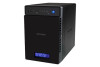
NETGEAR ReadyNAS 102 2 This chapter provides an overview of the physical features of the ReadyNAS 102 and includes the following sections: • Front and Side Panels • Drive Bays • Rear Panel • Status Information • Power On and Shut Down • Boot Menu 10 2.
NETGEAR ReadyNAS 102 2 This chapter provides an overview of the physical features of the ReadyNAS 102 and includes the following sections: • Front and Side Panels • Drive Bays • Rear Panel • Status Information • Power On and Shut Down • Boot Menu 10 2.

Hardware Manual
Page 11
Disk activity LED 3. Drive bay door 4 567 NETGEAR ReadyNAS 102 11 USB and Backup status LED 7. Disk 1 and Disk 2 LEDs 8. Exhaust vent 4. Backup button 6. ReadyNAS OS 6 Desktop Storage Systems Front and Side Panels The following figure shows the front and side panels of the ReadyNAS 102. 1 2 3 8 Figure 1. USB 2.0 port 5. ReadyNAS 102 front and side panels 1. Power button and LED 2.
Disk activity LED 3. Drive bay door 4 567 NETGEAR ReadyNAS 102 11 USB and Backup status LED 7. Disk 1 and Disk 2 LEDs 8. Exhaust vent 4. Backup button 6. ReadyNAS OS 6 Desktop Storage Systems Front and Side Panels The following figure shows the front and side panels of the ReadyNAS 102. 1 2 3 8 Figure 1. USB 2.0 port 5. ReadyNAS 102 front and side panels 1. Power button and LED 2.

Hardware Manual
Page 12
ReadyNAS OS 6 Desktop Storage Systems Drive Bays The following figure shows the drive bays of the ReadyNAS 102. 1 2 3 4 5 Figure 2. Drive bay door 2. Drive bays NETGEAR ReadyNAS 102 12 Disk tray handle 3. ReadyNAS 102 drive bays 1. Disk tray release latch 5. Recessed disk tray handle lock 4.
ReadyNAS OS 6 Desktop Storage Systems Drive Bays The following figure shows the drive bays of the ReadyNAS 102. 1 2 3 4 5 Figure 2. Drive bay door 2. Drive bays NETGEAR ReadyNAS 102 12 Disk tray handle 3. ReadyNAS 102 drive bays 1. Disk tray release latch 5. Recessed disk tray handle lock 4.
Hardware Manual
Page 14
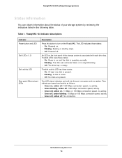
... the indicators listed in the following table. The disk was removed, failed, or is associated with each drive bay. A disk is operating normally. • Blinking. NETGEAR ReadyNAS 102 14 Two LED status indicators are present. ReadyNAS 102 indicator descriptions Indicator Power button and LED Disk ...the disk is active. • Off. Power is on . • Blinking. The LED indicates these states: • On. The drive bay is present. • Blinking. At least one amber. ReadyNAS OS 6 Desktop Storage Systems Status Information You can obtain information about the status of...
... the indicators listed in the following table. The disk was removed, failed, or is associated with each drive bay. A disk is operating normally. • Blinking. NETGEAR ReadyNAS 102 14 Two LED status indicators are present. ReadyNAS 102 indicator descriptions Indicator Power button and LED Disk ...the disk is active. • Off. Power is on . • Blinking. The LED indicates these states: • On. The drive bay is present. • Blinking. At least one amber. ReadyNAS OS 6 Desktop Storage Systems Status Information You can obtain information about the status of...

Hardware Manual
Page 18
NETGEAR ReadyNAS 104 3 This chapter provides an overview of the physical features of the ReadyNAS 104 and includes the following sections: • Front and Side Panels • Drive Bays • Rear Panel • Status Information • Power On and Shut Down • Boot Menu 18 3.
NETGEAR ReadyNAS 104 3 This chapter provides an overview of the physical features of the ReadyNAS 104 and includes the following sections: • Front and Side Panels • Drive Bays • Rear Panel • Status Information • Power On and Shut Down • Boot Menu 18 3.

Hardware Manual
Page 19
Disk activity LED 6. Drive bay door 8. Status display screen NETGEAR ReadyNAS 104 19 Exhaust vents 2. USB 2.0 port 3. Power button and LED 7. Disk LEDs 5. ReadyNAS 104 front and side panels 1. Backup button and LED 4. ReadyNAS OS 6 Desktop Storage Systems Front and Side Panels The following figure shows the front and side panels of the ReadyNAS 104. 23 4 56 1 7 8 Figure 4.
Disk activity LED 6. Drive bay door 8. Status display screen NETGEAR ReadyNAS 104 19 Exhaust vents 2. USB 2.0 port 3. Power button and LED 7. Disk LEDs 5. ReadyNAS 104 front and side panels 1. Backup button and LED 4. ReadyNAS OS 6 Desktop Storage Systems Front and Side Panels The following figure shows the front and side panels of the ReadyNAS 104. 23 4 56 1 7 8 Figure 4.

Hardware Manual
Page 20
Recessed disk tray handle lock 4. Drive bay door 2. Disk tray handle 3. Drive bays NETGEAR ReadyNAS 104 20 ReadyNAS OS 6 Desktop Storage Systems Drive Bays The following figure shows the drive bays of the ReadyNAS 104. 2 3 4 1 5 Figure 5. Disk tray release latch 5. ReadyNAS 104 drive bays 1.
Recessed disk tray handle lock 4. Drive bay door 2. Disk tray handle 3. Drive bays NETGEAR ReadyNAS 104 20 ReadyNAS OS 6 Desktop Storage Systems Drive Bays The following figure shows the drive bays of the ReadyNAS 104. 2 3 4 1 5 Figure 5. Disk tray release latch 5. ReadyNAS 104 drive bays 1.
Hardware Manual
Page 22
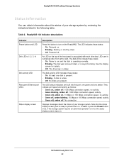
...bay is active. • Off. No connection. If the storage system reports an abnormal operation or error, the status display screen stays on . • Blinking. See the display screen for details. • Off. The disk activity LED indicates these states: • On. No disks are built into this button to right. NETGEAR...on the top of the front panel is operating normally. • Blinking. An LED on and the disk is associated with each drive bay. The disk was removed, failed, or is present. • Blinking. Note that the status display screen goes to sleep to prevent...
...bay is active. • Off. No connection. If the storage system reports an abnormal operation or error, the status display screen stays on . • Blinking. See the display screen for details. • Off. The disk activity LED indicates these states: • On. No disks are built into this button to right. NETGEAR...on the top of the front panel is operating normally. • Blinking. An LED on and the disk is associated with each drive bay. The disk was removed, failed, or is present. • Blinking. Note that the status display screen goes to sleep to prevent...

Hardware Manual
Page 27
4. NETGEAR ReadyNAS 202 4 This chapter provides an overview of the physical features of the ReadyNAS 202 and includes the following sections: • Front and Side Panels • Drive Bays • Rear Panel • Status Information • Power On and Shut Down • Boot Menu 27
4. NETGEAR ReadyNAS 202 4 This chapter provides an overview of the physical features of the ReadyNAS 202 and includes the following sections: • Front and Side Panels • Drive Bays • Rear Panel • Status Information • Power On and Shut Down • Boot Menu 27

Hardware Manual
Page 28
Exhaust vent 4. USB 3.0 port 5. USB and backup status LED 7. Disk 1 and Disk 2 LEDs 8. Drive bay door 4 567 NETGEAR ReadyNAS 202 28 Backup button 6. Disk activity LED 3. ReadyNAS OS 6 Desktop Storage Systems Front and Side Panels The following figure shows the front and side panels of the ReadyNAS 202. 1 2 3 8 Figure 7. ReadyNAS 202 front and side panels 1. Power button and LED 2.
Exhaust vent 4. USB 3.0 port 5. USB and backup status LED 7. Disk 1 and Disk 2 LEDs 8. Drive bay door 4 567 NETGEAR ReadyNAS 202 28 Backup button 6. Disk activity LED 3. ReadyNAS OS 6 Desktop Storage Systems Front and Side Panels The following figure shows the front and side panels of the ReadyNAS 202. 1 2 3 8 Figure 7. ReadyNAS 202 front and side panels 1. Power button and LED 2.

Hardware Manual
Page 29
Disk tray handle 3. Drive bay door 2. ReadyNAS OS 6 Desktop Storage Systems Drive Bays The following figure shows the drive bays of the ReadyNAS 202. 1 2 3 4 5 Figure 8. Recessed disk tray handle lock 4. Disk tray release latch 5. Drive bays NETGEAR ReadyNAS 202 29 ReadyNAS 202 drive bays 1.
Disk tray handle 3. Drive bay door 2. ReadyNAS OS 6 Desktop Storage Systems Drive Bays The following figure shows the drive bays of the ReadyNAS 202. 1 2 3 4 5 Figure 8. Recessed disk tray handle lock 4. Disk tray release latch 5. Drive bays NETGEAR ReadyNAS 202 29 ReadyNAS 202 drive bays 1.
Hardware Manual
Page 31
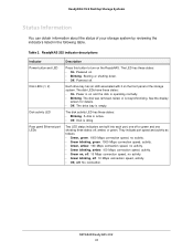
... 2) Disk activity LED Rear panel Ethernet port LEDs Description Press this button to turn on . • Blinking. The drive bay is idling. Disk is empty. They indicate port speed and activity as follows: • Green, green. 1000 Mbps connection ...showing three states: off, amber, or green. The LED has these states: • On. Each drive bay has an LED associated with it on and the disk is on the front panel of your storage system by ... Storage Systems Status Information You can obtain information about the status of the storage system. NETGEAR ReadyNAS 202 31
... 2) Disk activity LED Rear panel Ethernet port LEDs Description Press this button to turn on . • Blinking. The drive bay is idling. Disk is empty. They indicate port speed and activity as follows: • Green, green. 1000 Mbps connection ...showing three states: off, amber, or green. The LED has these states: • On. Each drive bay has an LED associated with it on and the disk is on the front panel of your storage system by ... Storage Systems Status Information You can obtain information about the status of the storage system. NETGEAR ReadyNAS 202 31

Hardware Manual
Page 37
5. NETGEAR ReadyNAS 204 5 This chapter provides an overview of the physical features of the ReadyNAS 204 and includes the following sections: • Front and Side Panels • Drive Bays • Rear Panel • Status Information • Power On and Shut Down • Boot Menu 37
5. NETGEAR ReadyNAS 204 5 This chapter provides an overview of the physical features of the ReadyNAS 204 and includes the following sections: • Front and Side Panels • Drive Bays • Rear Panel • Status Information • Power On and Shut Down • Boot Menu 37

Hardware Manual
Page 38
Exhaust vents 2. USB 2.0 port 3. Backup button and LED 4. Power button and LED 7. ReadyNAS OS 6 Desktop Storage Systems Front and Side Panels The following figure shows the front and side panels of the ReadyNAS 204. 23 4 56 1 7 8 Figure 11. Disk LEDs 5. Status display screen NETGEAR ReadyNAS 204 38 Disk activity LED 6. Drive bay door 8. ReadyNAS 204 front and side panels 1.
Exhaust vents 2. USB 2.0 port 3. Backup button and LED 4. Power button and LED 7. ReadyNAS OS 6 Desktop Storage Systems Front and Side Panels The following figure shows the front and side panels of the ReadyNAS 204. 23 4 56 1 7 8 Figure 11. Disk LEDs 5. Status display screen NETGEAR ReadyNAS 204 38 Disk activity LED 6. Drive bay door 8. ReadyNAS 204 front and side panels 1.

Hardware Manual
Page 39
ReadyNAS 204 drive bays 1. Drive bay door 2. Disk tray handle 3. Disk tray release latch 5. Recessed disk tray handle lock 4. Drive bays NETGEAR ReadyNAS 204 39 ReadyNAS OS 6 Desktop Storage Systems Drive Bays The following figure shows the drive bays of the ReadyNAS 204. 2 3 4 1 5 Figure 12.
ReadyNAS 204 drive bays 1. Drive bay door 2. Disk tray handle 3. Disk tray release latch 5. Recessed disk tray handle lock 4. Drive bays NETGEAR ReadyNAS 204 39 ReadyNAS OS 6 Desktop Storage Systems Drive Bays The following figure shows the drive bays of the ReadyNAS 204. 2 3 4 1 5 Figure 12.