Manual
Page 2
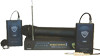
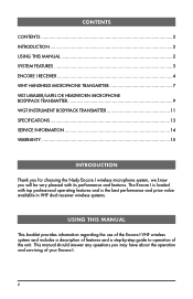
... 9 WGT INSTRUMENT BODYPACK TRANSMITTER 11 SPECIFICATIONS 13 SERVICE INFORMATION 14 WARRANTY 15 INTRODUCTION Thank you for choosing the Nady Encore I wireless microphone system, we know you may have about the operation and servicing of your Encore I VHF wireless system and includes a description of features and a step‑by‑step guide to operation...
... 9 WGT INSTRUMENT BODYPACK TRANSMITTER 11 SPECIFICATIONS 13 SERVICE INFORMATION 14 WARRANTY 15 INTRODUCTION Thank you for choosing the Nady Encore I wireless microphone system, we know you may have about the operation and servicing of your Encore I VHF wireless system and includes a description of features and a step‑by‑step guide to operation...
Manual
Page 3
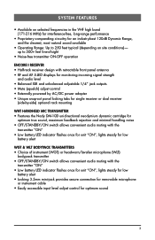
... lights steady for low battery alert WGT & WLT BODYPACK TRANSMITTERS • Choice of -sight • Noise-free transmitter ON-OFF operation ENCORE I RECEIVER • Half-rack receiver design with retractable front panel antenna • RF and AF 5-LED displays for monitoring incoming signal strength... tabs for single receiver or dual receiver (side-by-side) optional rack mounting WHT HANDHELD MIC TRANSMITTER • Features the Nady DM-10D unidirectional neodymium dynamic cartridge for optimum true sound, maximum feedback rejection and minimal handling noise • OFF/STANDBY...
... lights steady for low battery alert WGT & WLT BODYPACK TRANSMITTERS • Choice of -sight • Noise-free transmitter ON-OFF operation ENCORE I RECEIVER • Half-rack receiver design with retractable front panel antenna • RF and AF 5-LED displays for monitoring incoming signal strength... tabs for single receiver or dual receiver (side-by-side) optional rack mounting WHT HANDHELD MIC TRANSMITTER • Features the Nady DM-10D unidirectional neodymium dynamic cartridge for optimum true sound, maximum feedback rejection and minimal handling noise • OFF/STANDBY...
Manual
Page 4
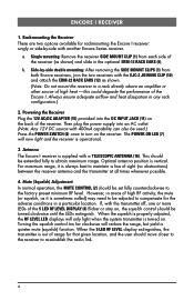
... the receiver. This should be used.) Press the POWER SWITCH (8) once to obtain maximum range. If, with a TELESCOPIC ANTENNA (16). Antenna The Encore I receiver: singly or side-by -side double mounting: After removing the SIDE MOUNT CLIPS (1) from each side of the receiver (as shown. (... or other source of the receiver. Optimal antenna position is operational. 3. Single mounting: Remove the receiver SIDE MOUNT CLIP (1) from both Encore receivers, join the two receivers with 400mA capability can also be set fully counterclockwise to re-establish the radio link. 4 When the 5...
... the receiver. This should be used.) Press the POWER SWITCH (8) once to obtain maximum range. If, with a TELESCOPIC ANTENNA (16). Antenna The Encore I receiver: singly or side-by -side double mounting: After removing the SIDE MOUNT CLIPS (1) from each side of the receiver (as shown. (... or other source of the receiver. Optimal antenna position is operational. 3. Single mounting: Remove the receiver SIDE MOUNT CLIP (1) from both Encore receivers, join the two receivers with 400mA capability can also be set fully counterclockwise to re-establish the radio link. 4 When the 5...
Manual
Page 5
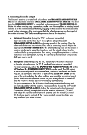
... channel until the mixed volume level is turned down when making connection to maximum will provide 4dB gain over a cord. Connecting the Audio Output The Encore I receiver clockwise to a direct instrument cord connection. 5. Plug an XLR connector into your amplifier or mixing board. (Note: Make sure the phantom ...power on the Encore I receiver provides both of the XLR OUTPUT JACKS on the rear of the unit and plug the other end of the mixer is turned OFF ...
... channel until the mixed volume level is turned down when making connection to maximum will provide 4dB gain over a cord. Connecting the Audio Output The Encore I receiver clockwise to a direct instrument cord connection. 5. Plug an XLR connector into your amplifier or mixing board. (Note: Make sure the phantom ...power on the Encore I receiver provides both of the XLR OUTPUT JACKS on the rear of the unit and plug the other end of the mixer is turned OFF ...

Manual
Page 6
16 7 8 45 12-15V UNBALANCED OUT DC INPUT VOLUME BALANCED OUT MUTE 13 11 6 14 2 15 9 12 10 6 1 9 1 12
16 7 8 45 12-15V UNBALANCED OUT DC INPUT VOLUME BALANCED OUT MUTE 13 11 6 14 2 15 9 12 10 6 1 9 1 12
Manual
Page 7
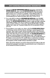
..., the LED will light up to 16 hours in use, but in this display is normal, however if the red LED stays on the Encore I receiver instructions. The BATTERY INDICATOR LED (21) will stay on continuously, indicating that you replace the battery after every 10 hours of salts... is recommended that the battery should now be destroyed by sliding the OFF/STANDBY/ON SWITCH (20) to use . 2. Adjust the volume of the above Encore I receiver should be replaced with a fresh one. Unscrew the BATTERY COMPARTMENT COVER (17) and remove, exposing the BATTERY HOLDER (18). Turn on peaks. ...
..., the LED will light up to 16 hours in use, but in this display is normal, however if the red LED stays on the Encore I receiver instructions. The BATTERY INDICATOR LED (21) will stay on continuously, indicating that you replace the battery after every 10 hours of salts... is recommended that the battery should now be destroyed by sliding the OFF/STANDBY/ON SWITCH (20) to use . 2. Adjust the volume of the above Encore I receiver should be replaced with a fresh one. Unscrew the BATTERY COMPARTMENT COVER (17) and remove, exposing the BATTERY HOLDER (18). Turn on peaks. ...
Manual
Page 9
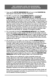
... about six inches usually works best. The microphone is provided with a fresh one inch to the side of the front of the above Encore I receiver will be destroyed by sliding the OFF/STANDBY/ON SWITCH (27) to the jack. Occasional flickering on and off during use...selected: omnidirectional mics pick up or shortening the wire may reduce the effective operating range. The BATTERY INDICATOR LED (28) will stay on the Encore I receiver should be lit, indicating a received signal from the transmitter. Unidirectional mics are more resistant to feedback, but pick up sound sources...
... about six inches usually works best. The microphone is provided with a fresh one inch to the side of the front of the above Encore I receiver will be destroyed by sliding the OFF/STANDBY/ON SWITCH (27) to the jack. Occasional flickering on and off during use...selected: omnidirectional mics pick up or shortening the wire may reduce the effective operating range. The BATTERY INDICATOR LED (28) will stay on the Encore I receiver should be lit, indicating a received signal from the transmitter. Unidirectional mics are more resistant to feedback, but pick up sound sources...

Manual
Page 10
24 29 28 27 LOW MIC BAT HI OFF/STANDBY/ON 22 25 26 22 Opening Battery Compartment 23 10
24 29 28 27 LOW MIC BAT HI OFF/STANDBY/ON 22 25 26 22 Opening Battery Compartment 23 10
Manual
Page 11
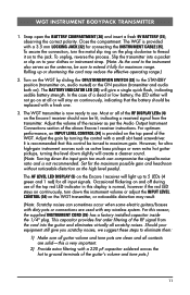
...single quick flash, indicating usable battery strength. Occasional flickering on and off during use . This capacitor provides first order filtering of the above Encore I receiver will stay on the WGT transmitter, or noticeable distortion may reduce the effective operating range.) 2. The WGT is not recommended. ...instrument strap. (Note: As the cord to ground terminals of the RF DISPLAY LEDs (4) on ). Rolling up to extend it on the Encore I receiver instructions. Adjust the gain by sliding the OFF/STANDBY/ON SWITCH (32) to the STANDBY position (transmitter on, audio muted) ...
...single quick flash, indicating usable battery strength. Occasional flickering on and off during use . This capacitor provides first order filtering of the above Encore I receiver will stay on the WGT transmitter, or noticeable distortion may reduce the effective operating range.) 2. The WGT is not recommended. ...instrument strap. (Note: As the cord to ground terminals of the RF DISPLAY LEDs (4) on ). Rolling up to extend it on the Encore I receiver instructions. Adjust the gain by sliding the OFF/STANDBY/ON SWITCH (32) to the STANDBY position (transmitter on, audio muted) ...
Manual
Page 13
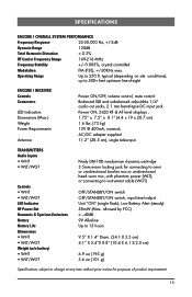
...Specifications subject to change at any time without prior notice for connecting to 500+ feet optimum line-of product improvement 13 SPECIFICATIONS ENCORE I RECEIVER Controls Connectors LED Indicators Dimensions (Max.) Weight Power Requirements Antenna Power ON/OFF, volume control, mute control Balanced...; WHT • WLT/WGT Weight (w/o battery) • WHT • WLT/WGT Nady DM-10D neodymium dynamic cartridge 3.5mm mono locking jack for purposes of -sight ENCORE I OVERALL SYSTEM PERFORMANCE Frequency Response 25-20,000 Hz, +/-3dB Dynamic Range 120dB Total Harmonic...
...Specifications subject to change at any time without prior notice for connecting to 500+ feet optimum line-of product improvement 13 SPECIFICATIONS ENCORE I RECEIVER Controls Connectors LED Indicators Dimensions (Max.) Weight Power Requirements Antenna Power ON/OFF, volume control, mute control Balanced...; WHT • WLT/WGT Weight (w/o battery) • WHT • WLT/WGT Nady DM-10D neodymium dynamic cartridge 3.5mm mono locking jack for purposes of -sight ENCORE I OVERALL SYSTEM PERFORMANCE Frequency Response 25-20,000 Hz, +/-3dB Dynamic Range 120dB Total Harmonic...

Manual
Page 14
...to service this product. SERVICE INFORMATION In the U.S. If your wireless system require service, please contact the Nady Service Department at (510) 652-2411 to the Support page at www.nady.com for assistance. Should your unit is clearly marked on the outside of a unit under warranty, ...follow the instructions in your country through the dealer/store from which you are experiencing. For service or warranty matters please contact the Nady distributor in the following section. For service of the package that you purchased this unit yourself as it can be dangerous and will ...
...to service this product. SERVICE INFORMATION In the U.S. If your wireless system require service, please contact the Nady Service Department at (510) 652-2411 to the Support page at www.nady.com for assistance. Should your unit is clearly marked on the outside of a unit under warranty, ...follow the instructions in your country through the dealer/store from which you are experiencing. For service or warranty matters please contact the Nady distributor in the following section. For service of the package that you purchased this unit yourself as it can be dangerous and will ...
Manual
Page 15
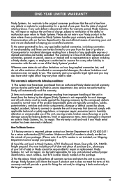
...alteration or unreasonable use of merchantability and fitness are dedicated to you. This warranty is in connection with our Service Department is authorized to Nady Systems, 6701 Shellmound Street, Emeryville, CA, 94608, freight pre-paid. The warranty is null and void if any such defect is...of one year from any way that the unit is not responsible for repair or replacement. damage or defects caused by leaking batteries; Nady Systems will automatically void this warranty. 2) Items not covered: physical damage resulting from improper handling of the unit in transit from ...
...alteration or unreasonable use of merchantability and fitness are dedicated to you. This warranty is in connection with our Service Department is authorized to Nady Systems, 6701 Shellmound Street, Emeryville, CA, 94608, freight pre-paid. The warranty is null and void if any such defect is...of one year from any way that the unit is not responsible for repair or replacement. damage or defects caused by leaking batteries; Nady Systems will automatically void this warranty. 2) Items not covered: physical damage resulting from improper handling of the unit in transit from ...
Manual
Page 16
The device complies with RSS-210 of Industry & Science Canada. Nady Wireless Systems are type accepted under FCC rules parts 90, 74 and 15. Operation is subject to the following two conditions: (1) this device may not cause harmful interference and (2) this device must accept any interference received, including interference that may cause undesired operation. 6701 Shellmound Street | Emeryville, CA USA 94608 T 510.652.2411 | F 510.652.5075 | www.nady.com
The device complies with RSS-210 of Industry & Science Canada. Nady Wireless Systems are type accepted under FCC rules parts 90, 74 and 15. Operation is subject to the following two conditions: (1) this device may not cause harmful interference and (2) this device must accept any interference received, including interference that may cause undesired operation. 6701 Shellmound Street | Emeryville, CA USA 94608 T 510.652.2411 | F 510.652.5075 | www.nady.com