Manual
Page 3
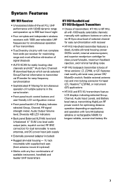
...all -metal housing; and operation with two AA batteries (alkaline or rechargeable NiMH) for lapel (LT), Headmic™ (LT/HM), or instrument (GT) applications • HT-1KU and BT-1KU transmitters feature LCD displays indicating selected Group, Channel, Audio Input Levels, and Battery level status; power... LCD configuration menus • Front panel backlit LCD display indicates selected Group, Channel, RF signal strength meter; System Features 4W-1KU Receiver • Unsurpassed state-of-the-art PLL UHF performance with 120dB dynamic range and operation up /down buttons on application...
...all -metal housing; and operation with two AA batteries (alkaline or rechargeable NiMH) for lapel (LT), Headmic™ (LT/HM), or instrument (GT) applications • HT-1KU and BT-1KU transmitters feature LCD displays indicating selected Group, Channel, Audio Input Levels, and Battery level status; power... LCD configuration menus • Front panel backlit LCD display indicates selected Group, Channel, RF signal strength meter; System Features 4W-1KU Receiver • Unsurpassed state-of-the-art PLL UHF performance with 120dB dynamic range and operation up /down buttons on application...

Manual
Page 7
... BATTERY COMPARTMENT DOOR 47. INPUT JACK 3.5mm locking mini jack for detail LCD display indicators. 41. BATTERY COMPARTMENT 46. Quick User Controls Guide BT-1KU Bodypack Transmitter (LT, LT/HM or GT) 30 31 32 37 38 39 40 41 42 33 43 44 45 46 47 48 37. LCD DISPLAY For indication... set for linking the TX to turn power on with audio muted 39. See 30/31/32/33 in HT-1KU transmitter diagram above for connecting audio input cord from lapel mic (LT), Headmic™ (LT/HM), or instrument (GT) 38. POWER OFF/MUTE/ON SWITCH Slide power switch to ON or OFF to...
... BATTERY COMPARTMENT DOOR 47. INPUT JACK 3.5mm locking mini jack for detail LCD display indicators. 41. BATTERY COMPARTMENT 46. Quick User Controls Guide BT-1KU Bodypack Transmitter (LT, LT/HM or GT) 30 31 32 37 38 39 40 41 42 33 43 44 45 46 47 48 37. LCD DISPLAY For indication... set for linking the TX to turn power on with audio muted 39. See 30/31/32/33 in HT-1KU transmitter diagram above for connecting audio input cord from lapel mic (LT), Headmic™ (LT/HM), or instrument (GT) 38. POWER OFF/MUTE/ON SWITCH Slide power switch to ON or OFF to...

Manual
Page 16
Synthesized PLL System Frequency Stability Frequency Response Dynamic Range Harmonic Distortion Modulation Operating Range (U.S.) Band 1: 672.000-696.975MHz, (Int.) Band 2: 795.000-819.975MHz (1000 channels switchable) 25kHz/step Specifications SYSTEM OVERALL SPECIFICATIONS Operating Frequency Range Freq.
Synthesized PLL System Frequency Stability Frequency Response Dynamic Range Harmonic Distortion Modulation Operating Range (U.S.) Band 1: 672.000-696.975MHz, (Int.) Band 2: 795.000-819.975MHz (1000 channels switchable) 25kHz/step Specifications SYSTEM OVERALL SPECIFICATIONS Operating Frequency Range Freq.