User Guide
Page 3
CONTENTS Contents 1 Safety 4 Introduction 5 Package Contents 5 Batteries and Chargers Safety Information 7 Operational Safety Guidelines 8 FCC Licensing Information 9 Interference Information 9 Radio Overview 11 Parts of the Radio 11 On/Off/Volume Knob 12 Channel Selector Knob 12 Accessory Connector 12 Model Label 12 Microphone 12 ... . 18 Attaching the Antenna 18 Removing the Antenna 18 Installing Spring Action Belt Clip 19 Power Supply, Adaptor and Drop-in Tray Charger 19 Battery Life Information 20 Alkaline Battery Life 21 Charging the Battery 22 1 English CONTENTS
CONTENTS Contents 1 Safety 4 Introduction 5 Package Contents 5 Batteries and Chargers Safety Information 7 Operational Safety Guidelines 8 FCC Licensing Information 9 Interference Information 9 Radio Overview 11 Parts of the Radio 11 On/Off/Volume Knob 12 Channel Selector Knob 12 Accessory Connector 12 Model Label 12 Microphone 12 ... . 18 Attaching the Antenna 18 Removing the Antenna 18 Installing Spring Action Belt Clip 19 Power Supply, Adaptor and Drop-in Tray Charger 19 Battery Life Information 20 Alkaline Battery Life 21 Charging the Battery 22 1 English CONTENTS

User Guide
Page 5
... Frequencies Chart 65 RDU2020 - CONTENTS Cloning Radios 51 Cloning with a Multi Unit Charger (MUC 51 Cloning Radio using the Radio to Radio (R2R) Cloning Cable (Optional Accessory 53 Cloning using the CPS (Computer Programming Software 55 Troubleshooting 56 Use and Care 60 Frequency and Code Charts 61 RDX VHF Frequencies Chart 61 RDV2020 - UHF Default Frequencies Chart...
... Frequencies Chart 65 RDU2020 - CONTENTS Cloning Radios 51 Cloning with a Multi Unit Charger (MUC 51 Cloning Radio using the Radio to Radio (R2R) Cloning Cable (Optional Accessory 53 Cloning using the CPS (Computer Programming Software 55 Troubleshooting 56 Use and Care 60 Frequency and Code Charts 61 RDX VHF Frequencies Chart 61 RDV2020 - UHF Default Frequencies Chart...

User Guide
Page 7
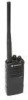
...Read this user guide carefully to properly operate the radio before use Business Radios, RPSD 1C15, Motorola 8000 West Sunrise Boulevard Plantation, Florida 33322 PACKAGE CONTENTS • Radio • Antenna (only for RDU4100 and RDV5100) • Spring Action Belt-Clip • ... purchasing the Motorola® RDX Series™ Radio. Motorola Business two-way radios are the perfect communications solution for businesses such as a world leader in Tray Charger • Product Safety & RF Exposure Booklet INTRODUCTION 5 English The RDX Series™ radios provide cost-effective...
...Read this user guide carefully to properly operate the radio before use Business Radios, RPSD 1C15, Motorola 8000 West Sunrise Boulevard Plantation, Florida 33322 PACKAGE CONTENTS • Radio • Antenna (only for RDU4100 and RDV5100) • Spring Action Belt-Clip • ... purchasing the Motorola® RDX Series™ Radio. Motorola Business two-way radios are the perfect communications solution for businesses such as a world leader in Tray Charger • Product Safety & RF Exposure Booklet INTRODUCTION 5 English The RDX Series™ radios provide cost-effective...

User Guide
Page 9
... and cord, pull by Motorola may result in risk of electrical shock or fire. 7. it is 18AWG for lengths up to 6.5 feet (2.0 m), and 16AWG for future reference. Before using the battery charger, read all the instructions and cautionary markings on • the charger, • the battery, and • the radio using the battery 1. An...
... and cord, pull by Motorola may result in risk of electrical shock or fire. 7. it is 18AWG for lengths up to 6.5 feet (2.0 m), and 16AWG for future reference. Before using the battery charger, read all the instructions and cautionary markings on • the charger, • the battery, and • the radio using the battery 1. An...
User Guide
Page 10
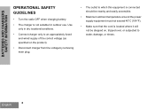
... to an appropriately fused and wired supply of the correct voltage (as specified on the product). • Disconnect charger from line voltage by removing main plug. • The outlet to which this equipment is connected should be nearby and easily accessible. • ...176;C (104°F). • Make sure that the cord is not suitable for outdoor use. BATTERIES AND CHARGERS SAFETY INFORMATION OPERATIONAL SAFETY GUIDELINES • Turn the radio OFF when charging battery. • The charger is located where it will not be stepped on, tripped over, or subjected to water, damage, or ...
... to an appropriately fused and wired supply of the correct voltage (as specified on the product). • Disconnect charger from line voltage by removing main plug. • The outlet to which this equipment is connected should be nearby and easily accessible. • ...176;C (104°F). • Make sure that the cord is not suitable for outdoor use. BATTERIES AND CHARGERS SAFETY INFORMATION OPERATIONAL SAFETY GUIDELINES • Turn the radio OFF when charging battery. • The charger is located where it will not be stepped on, tripped over, or subjected to water, damage, or ...

User Guide
Page 16
... 50% per day. It also offers the option to be used with a Motorola charger and vice versa. About the Li-Ion Battery The RDX Series™ radio comes equipped with each cycle. Battery life is overcharged and discharged 100% several factors. Motorola batteries are designed specifically to use to ensure that will last. Typically, the...
... 50% per day. It also offers the option to be used with a Motorola charger and vice versa. About the Li-Ion Battery The RDX Series™ radio comes equipped with each cycle. Battery life is overcharged and discharged 100% several factors. Motorola batteries are designed specifically to use to ensure that will last. Typically, the...
User Guide
Page 21
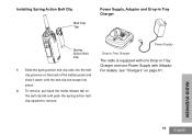
... belt clip tab and push the spring action belt clip upward to remove. For details, see "Chargers" on page 81. Power Supply Drop-in Tray Charger The radio is equipped with one Power Supply with Adaptor. RADIO OVERVIEW 19 English Installing Spring Action Belt Clip Belt Clip Tab Power Supply, Adaptor and Drop-in...
... belt clip tab and push the spring action belt clip upward to remove. For details, see "Chargers" on page 81. Power Supply Drop-in Tray Charger The radio is equipped with one Power Supply with Adaptor. RADIO OVERVIEW 19 English Installing Spring Action Belt Clip Belt Clip Tab Power Supply, Adaptor and Drop-in...

User Guide
Page 24
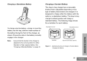
...radio comes equipped with a Standard Charger To charge the battery (with the radio attached), place it in a Motorola-approved Drop-in Tray Single Unit Charger or Drop-in tray chargers and power supplies sets (all "rapid" or all "standard"). Plug the AC adaptor into the tray with the Drop-in Tray Single Unit Charger... (SUC) Power Supply (Transformer) Drop-in Tray Charger Port Drop-in Tray Charger 1. Note: When acquiring additional chargers or power supplies, make sure you have similar drop-in Tray Multi Unit Charger. Charging the Battery RDX Series™ ...
...radio comes equipped with a Standard Charger To charge the battery (with the radio attached), place it in a Motorola-approved Drop-in Tray Single Unit Charger or Drop-in tray chargers and power supplies sets (all "rapid" or all "standard"). Plug the AC adaptor into the tray with the Drop-in Tray Single Unit Charger... (SUC) Power Supply (Transformer) Drop-in Tray Charger Port Drop-in Tray Charger 1. Note: When acquiring additional chargers or power supplies, make sure you have similar drop-in Tray Multi Unit Charger. Charging the Battery RDX Series™ ...
User Guide
Page 25
... battery: Adjustable bracket Adjustable bracket Standard High and Ultra High Capacity Figure 1: Identifying the Drop-In Charger's Position Before Charging the Battery RADIO OVERVIEW 23 English Ensure the slots in the battery correctly engage in the charger Note: Ensure that is adjustable depending on page 23 Charging a Standard Battery The drop-in tray...
... battery: Adjustable bracket Adjustable bracket Standard High and Ultra High Capacity Figure 1: Identifying the Drop-In Charger's Position Before Charging the Battery RADIO OVERVIEW 23 English Ensure the slots in the battery correctly engage in the charger Note: Ensure that is adjustable depending on page 23 Charging a Standard Battery The drop-in tray...
User Guide
Page 26
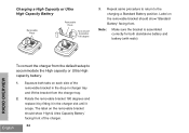
...battery and battery (with radio) To convert the charger from the charger tray. 2. The label on the removable bracket should show 'High & Ultra Capacity Battery' facing front of the removable bracket in the drop-in the charger slot until it snaps. Label on each side of the charger. English 24 Rotate ...the removable bracket 180 degrees and replace it by fitting it in charger tray and lift the bracket from the default setup to the ...
...battery and battery (with radio) To convert the charger from the charger tray. 2. The label on the removable bracket should show 'High & Ultra Capacity Battery' facing front of the removable bracket in the drop-in the charger slot until it snaps. Label on each side of the charger. English 24 Rotate ...the removable bracket 180 degrees and replace it by fitting it in charger tray and lift the bracket from the default setup to the ...
User Guide
Page 27
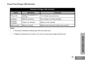
Drop-in Tray Charger LED Indicators Standard Charger LED Indicator Status Power ON Charging Charging Complete Battery Fault(*) LED Status Steady red indication for 3 seconds Blinking red (slow) Steady red indication Blinking red (fast) Comments The charger has powered up The charger is currently charging Battery is fully charged Battery had a fault when battery was inserted Notes: • (*) Normally re-seating the battery pack will correct this issue. • (**) Battery temperature is too warm or too cold or wrong power supply is being used RADIO OVERVIEW 25 English
Drop-in Tray Charger LED Indicators Standard Charger LED Indicator Status Power ON Charging Charging Complete Battery Fault(*) LED Status Steady red indication for 3 seconds Blinking red (slow) Steady red indication Blinking red (fast) Comments The charger has powered up The charger is currently charging Battery is fully charged Battery had a fault when battery was inserted Notes: • (*) Normally re-seating the battery pack will correct this issue. • (**) Battery temperature is too warm or too cold or wrong power supply is being used RADIO OVERVIEW 25 English
User Guide
Page 28
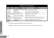
... Indicator Status LED Status Comments Power ON Charging Steady green indication for 3 seconds The charger has powered up Blinking green The charger is currently charging Top-off Charging Blinking green (slow) Battery is near fully charged Charge Complete Steady green indication Battery is fully charged Battery Fault (*) ... re-seating the battery pack will correct this issue. • (**) Battery temperature is too warm or too cold or wrong power supply is being used RADIO OVERVIEW English 26
... Indicator Status LED Status Comments Power ON Charging Steady green indication for 3 seconds The charger has powered up Blinking green The charger is currently charging Top-off Charging Blinking green (slow) Battery is near fully charged Charge Complete Steady green indication Battery is fully charged Battery Fault (*) ... re-seating the battery pack will correct this issue. • (**) Battery temperature is too warm or too cold or wrong power supply is being used RADIO OVERVIEW English 26
User Guide
Page 30
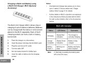
...power cord plug into an AC outlet. Batteries can hold a radio or battery, but not both. RADIO OVERVIEW 1. 2. 3. 4. 5. 6. Turn the radio OFF. MUC LED Indicator Status LED Status Comments Charging Steady Red Indication The charger is currently charging Charge Complete Steady Green Indication Battery is fully ... the battery pack will correct this issue. English Place the charger on MUC's operation are explained in the Instructions Sheet provided with the radios or removed and placed in charging of up to 6 radios or batteries. For part number details, refer to page 51...
...power cord plug into an AC outlet. Batteries can hold a radio or battery, but not both. RADIO OVERVIEW 1. 2. 3. 4. 5. 6. Turn the radio OFF. MUC LED Indicator Status LED Status Comments Charging Steady Red Indication The charger is currently charging Charge Complete Steady Green Indication Battery is fully ... the battery pack will correct this issue. English Place the charger on MUC's operation are explained in the Instructions Sheet provided with the radios or removed and placed in charging of up to 6 radios or batteries. For part number details, refer to page 51...

User Guide
Page 50
... Software is by giving the option to Features Summary Chart Section at : www.motorolasolutions.com/RDX To program, connect the RDX Series™ radio via the Drop-in Charger Tray and CPS Programming Cable as shown in your Motorola point of the user guide for more information. CPS allows the user to program frequencies, PL...
... Software is by giving the option to Features Summary Chart Section at : www.motorolasolutions.com/RDX To program, connect the RDX Series™ radio via the Drop-in Charger Tray and CPS Programming Cable as shown in your Motorola point of the user guide for more information. CPS allows the user to program frequencies, PL...

User Guide
Page 53
... of these 3 methods: • a Multi Unit Charger (optional accessory), • Two Single Unit Chargers (SUC) and a Radio-to- Turn ON the Target radio and place it into a power source, but ALL radios require charged batteries. 1. PROGRAMMING FEATURES CLONING RADIOS You can clone RDX Series™ radio profiles from the source radio.) The Source radio has to be in the MUCs...
... of these 3 methods: • a Multi Unit Charger (optional accessory), • Two Single Unit Chargers (SUC) and a Radio-to- Turn ON the Target radio and place it into a power source, but ALL radios require charged batteries. 1. PROGRAMMING FEATURES CLONING RADIOS You can clone RDX Series™ radio profiles from the source radio.) The Source radio has to be in the MUCs...
User Guide
Page 55
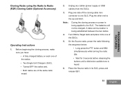
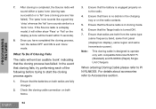
... process no power is being established between the two radios. 4. Plug the other end to one SUC. Turn ON the Target radio and place it into one of the radios. • Two Single Unit Chargers (SUC). • Turned OFF the radios and, • Both radios are of the cloning cable mini connector to the... second SUC. Place the Source radio in its SUC, press and release SB1....
... process no power is being established between the two radios. 4. Plug the other end to one SUC. Turn ON the Target radio and place it into one of the radios. • Two Single Unit Chargers (SUC). • Turned OFF the radios and, • Both radios are of the cloning cable mini connector to the... second SUC. Place the Source radio in its SUC, press and release SB1....
User Guide
Page 56
... fully charged. 2. Ensure that the Source radio is a display model, it will either a 'pass' tone (cloning was successful) or a 'fail' tone (cloning process has failed). When ordering Cloning Cable please refer to operate only with compatible Motorola RLN6175 (Standard) and RLN6304 (Rapid) Single Unit Chargers. English 54 Note: This cloning cable is no...
... fully charged. 2. Ensure that the Source radio is a display model, it will either a 'pass' tone (cloning was successful) or a 'fail' tone (cloning process has failed). When ordering Cloning Cable please refer to operate only with compatible Motorola RLN6175 (Standard) and RLN6304 (Rapid) Single Unit Chargers. English 54 Note: This cloning cable is no...
User Guide
Page 57
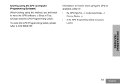
To order the CPS Programming Cable, please refer to have the CPS software, a Drop-in the CPS Programming Cable Accessory Leaflet. Information on how to clone using this method, you will need to P/N RKN4155. PROGRAMMING FEATURES 55 English Cloning using the CPS (Computer Programming Software) When cloning using the CPS is available either in: • the CPS Help File --> Content and Index --> Cloning Radios, or • in Tray Charger and the CPS Programming Cable.
To order the CPS Programming Cable, please refer to have the CPS software, a Drop-in the CPS Programming Cable Accessory Leaflet. Information on how to clone using this method, you will need to P/N RKN4155. PROGRAMMING FEATURES 55 English Cloning using the CPS (Computer Programming Software) When cloning using the CPS is available either in: • the CPS Help File --> Content and Index --> Cloning Radios, or • in Tray Charger and the CPS Programming Cable.
User Guide
Page 60
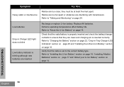
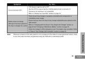
...that they must be at least five feet apart. they are too close; Radios are clean and charging pin is properly inserted and check the battery/charger contacts to "About the Li-Ion Battery" on page 16. Radios are too far apart or obstacles are inserted Recharge or replace Li-Ion battery.... Low batteries Drop-in Tray Charger LED Indicators" section on page 25 and "Installing the...
...that they must be at least five feet apart. they are too close; Radios are clean and charging pin is properly inserted and check the battery/charger contacts to "About the Li-Ion Battery" on page 16. Radios are too far apart or obstacles are inserted Recharge or replace Li-Ion battery.... Low batteries Drop-in Tray Charger LED Indicators" section on page 25 and "Installing the...
User Guide
Page 61
... indicators to '0'. Cannot activate VOX VOX feature might be set to see if the radio has been programmed using the CPS with the Drop-In Tray Single Unit Charger" section on page 22 and "Charging a Standalone Battery" section on page 33. Use the CPS to ensure that you have the drop...-in the radio seems to not correspond to the default or preprogrammed values, check to a ...
... indicators to '0'. Cannot activate VOX VOX feature might be set to see if the radio has been programmed using the CPS with the Drop-In Tray Single Unit Charger" section on page 22 and "Charging a Standalone Battery" section on page 33. Use the CPS to ensure that you have the drop...-in the radio seems to not correspond to the default or preprogrammed values, check to a ...


