
Operating and Installation manual
Page 1
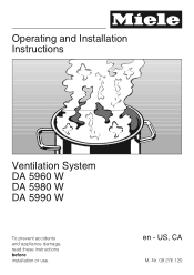
US, CA M.-Nr. 09 276 120 Operating and Installation Instructions Ventilation System DA 5960 W DA 5980 W DA 5990 W To prevent accidents and appliance damage, read these instructions before installation or use. en -
US, CA M.-Nr. 09 276 120 Operating and Installation Instructions Ventilation System DA 5960 W DA 5980 W DA 5990 W To prevent accidents and appliance damage, read these instructions before installation or use. en -
Operating and Installation manual
Page 2
... SAFETY INSTRUCTIONS 3 Functional description 7 Guide to the Ventilation System 8 Operation 10 Turning on the fan 10 Selecting the power level 10 Turning off the fan 12 Turning the lighting On/Off 12 Cleaning and Care 13 Cleaning the casing 13 Grease filter 14 Active charcoal filter 16 Changing the light bulbs 17 After Sales Service 18 Installation instructions 19 Caring for the environment 21 Appliance dimensions 22 Installation accessories 26 Plywood backing 28 Installation 29 Dismantling 29 Air extraction 30 Electrical connection 32...
... SAFETY INSTRUCTIONS 3 Functional description 7 Guide to the Ventilation System 8 Operation 10 Turning on the fan 10 Selecting the power level 10 Turning off the fan 12 Turning the lighting On/Off 12 Cleaning and Care 13 Cleaning the casing 13 Grease filter 14 Active charcoal filter 16 Changing the light bulbs 17 After Sales Service 18 Installation instructions 19 Caring for the environment 21 Appliance dimensions 22 Installation accessories 26 Plywood backing 28 Installation 29 Dismantling 29 Air extraction 30 Electrical connection 32...
Operating and Installation manual
Page 3
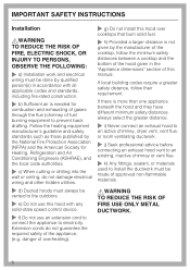
... is not intended for installation above gas or electric cooking surfaces. ~ This appliance is any future user. Use the appliance only for residential use . ~ This appliance must exist between the appliance and an effective grounding system. Do Not Use To Exhaust Hazardous Or Explosive Materials And Vapors. ~ This appliance is designed to prevent power from being switched on a ship). ,WARNING TO REDUCE THE...
... is not intended for installation above gas or electric cooking surfaces. ~ This appliance is any future user. Use the appliance only for residential use . ~ This appliance must exist between the appliance and an effective grounding system. Do Not Use To Exhaust Hazardous Or Explosive Materials And Vapors. ~ This appliance is designed to prevent power from being switched on a ship). ,WARNING TO REDUCE THE...
Operating and Installation manual
Page 4
... described in the enclosed "Installation diagram" and in the "Cleaning and care" section of this manual. Repairs and other parts of the cooking area. ~ e) Do not flambé or grill with electrical connections or components and mechanical parts is highly dangerous to the user and can cause operation faults. ~ g) Before discarding an old appliance, disconnect it from the power supply and remove the power cord to prevent hazards. Boilovers...
... described in the enclosed "Installation diagram" and in the "Cleaning and care" section of this manual. Repairs and other parts of the cooking area. ~ e) Do not flambé or grill with electrical connections or components and mechanical parts is highly dangerous to the user and can cause operation faults. ~ g) Before discarding an old appliance, disconnect it from the power supply and remove the power cord to prevent hazards. Boilovers...

Operating and Installation manual
Page 5
... PAN - when using the cooktop to prevent damage from the burners and the cookware. ~ Do not use the hood without cookware. BE CAREFUL TO PREVENT BURNS. You may be damaged due to excessive heat from condensation. ~ Never operate gas burners without the grease filters in place. ~ Do not use . Steam could penetrate electrical components and cause a short circuit. 5 Supervise its use by NAFTA...
... PAN - when using the cooktop to prevent damage from the burners and the cookware. ~ Do not use the hood without cookware. BE CAREFUL TO PREVENT BURNS. You may be damaged due to excessive heat from condensation. ~ Never operate gas burners without the grease filters in place. ~ Do not use . Steam could penetrate electrical components and cause a short circuit. 5 Supervise its use by NAFTA...
Operating and Installation manual
Page 6
.... ~ j) Seek professional advice before connecting an exhaust hood vent to an existing, inactive chimney or vent flue. ~ k) Any fittings, sealant, or materials used to install the ductwork must always be vented to the outdoors. ~ e) Do not use an extension cord to connect the appliance to electricity. Follow the heating equipment manufacturer's guideline and safety standards such as those published by the manufacturer of the cooktop, follow their requirement.
.... ~ j) Seek professional advice before connecting an exhaust hood vent to an existing, inactive chimney or vent flue. ~ k) Any fittings, sealant, or materials used to install the ductwork must always be vented to the outdoors. ~ e) Do not use an extension cord to connect the appliance to electricity. Follow the heating equipment manufacturer's guideline and safety standards such as those published by the manufacturer of the cooktop, follow their requirement.
Operating and Installation manual
Page 7
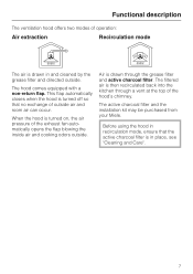
... active charcoal filter and the installation kit may be purchased from your Miele. This flap automatically closes when the hood is turned off so that the active charcoal filter is drawn through a vent at the top of the exhaust fan automatically opens the flap blowing the inside air and cooking odors outside . When the hood is then recirculated back into the kitchen through the grease filter and active charcoal filter. Air is in recirculation...
... active charcoal filter and the installation kit may be purchased from your Miele. This flap automatically closes when the hood is turned off so that the active charcoal filter is drawn through a vent at the top of the exhaust fan automatically opens the flap blowing the inside air and cooking odors outside . When the hood is then recirculated back into the kitchen through the grease filter and active charcoal filter. Air is in recirculation...
Operating and Installation manual
Page 13
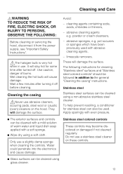
... time after turning it from the power supply, see "Important Safety Instructions". ,The halogen bulb is very hot when in addition to the general "Cleaning the casing" instructions. abrasive sponges, e.g. Use caution, danger of warm water and liquid dish soap applied with abrasive cleaning agents, - Cleaning the casing ,Never use abrasive cleaners, scouring pads, steel wool or caustic (oven) cleaners on these controls. ^ Glass...
... time after turning it from the power supply, see "Important Safety Instructions". ,The halogen bulb is very hot when in addition to the general "Cleaning the casing" instructions. abrasive sponges, e.g. Use caution, danger of warm water and liquid dish soap applied with abrasive cleaning agents, - Cleaning the casing ,Never use abrasive cleaners, scouring pads, steel wool or caustic (oven) cleaners on these controls. ^ Glass...

Operating and Installation manual
Page 17
.... Cleaning and Care Changing the light bulbs ,WARNING TO REDUCE THE RISK OF FIRE, ELECTRIC SHOCK, OR INJURY TO PERSONS, OBSERVE THE FOLLOWING: Before changing the light bulbs, disconnect the hood from the fixture. dai2409 ^ Use the button above the lamp housing to press the lighting unit slightly downward ^ Then turn the halogen light to the left to cool. Do not touch the bulb surface. Use the same bulb type as a replacement. ^ Screw...
.... Cleaning and Care Changing the light bulbs ,WARNING TO REDUCE THE RISK OF FIRE, ELECTRIC SHOCK, OR INJURY TO PERSONS, OBSERVE THE FOLLOWING: Before changing the light bulbs, disconnect the hood from the fixture. dai2409 ^ Use the button above the lamp housing to press the lighting unit slightly downward ^ Then turn the halogen light to the left to cool. Do not touch the bulb surface. Use the same bulb type as a replacement. ^ Screw...
Operating and Installation manual
Page 18
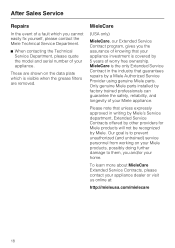
... your appliance investment is covered by 5 years of worry free ownership. MieleCare is to prevent unauthorized (and untrained) service personnel from working on the data plate which you cannot easily fix yourself, please contact the Miele Technical Service Department. ^ When contacting the Technical Service Department, please quote the model and serial number of your appliance. Only genuine Miele parts installed by Miele. Our goal is...
... your appliance investment is covered by 5 years of worry free ownership. MieleCare is to prevent unauthorized (and untrained) service personnel from working on the data plate which you cannot easily fix yourself, please contact the Miele Technical Service Department. ^ When contacting the Technical Service Department, please quote the model and serial number of your appliance. Only genuine Miele parts installed by Miele. Our goal is...

Operating and Installation manual
Page 23
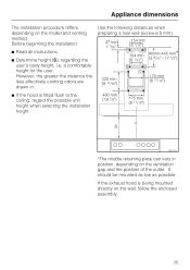
... and height of the tiles or panel. Appliance dimensions 1) Air extraction mode 2) Recirculation mode 3) Recirculation vent installed upwards 4) and 5) Installation area Wall/ceiling area respectively for vent hole and outlet installation. dai2479 23 Ductwork ø 6" (150 mm), with reducing collar ø 5" (125 mm) 6) If you plan to have a tiled backsplash or wall panel underneath the exhaust hood, this is the case the filter needs to be turned 180° and inserted...
... and height of the tiles or panel. Appliance dimensions 1) Air extraction mode 2) Recirculation mode 3) Recirculation vent installed upwards 4) and 5) Installation area Wall/ceiling area respectively for vent hole and outlet installation. dai2479 23 Ductwork ø 6" (150 mm), with reducing collar ø 5" (125 mm) 6) If you plan to have a tiled backsplash or wall panel underneath the exhaust hood, this is the case the filter needs to be turned 180° and inserted...

Operating and Installation manual
Page 24
... between cooktop and hood (S) Do not install this exhaust hood over cooktops burning solid fuel. upper cabinets. - If several gas surfaces are installed under the hood, the total output must be considered when determining the minimum safety distance. - If local building codes require a greater safety distance, follow the minimum safety distances given by the manufacturer of the hood: Electric Cooktops Electric Barbeques and Fryers Multiburner Gas cooktops < 43...
... between cooktop and hood (S) Do not install this exhaust hood over cooktops burning solid fuel. upper cabinets. - If several gas surfaces are installed under the hood, the total output must be considered when determining the minimum safety distance. - If local building codes require a greater safety distance, follow the minimum safety distances given by the manufacturer of the hood: Electric Cooktops Electric Barbeques and Fryers Multiburner Gas cooktops < 43...
Operating and Installation manual
Page 25
... exhaust hood is fitted flush to the ceiling, regard the possible unit height when selecting the installation height. *The middle retaining plate can vary in . ^ If the hood is being mounted directly on the model and venting method. a comfortable height for the user. It should be mounted as low as possible. Before beginning the installation: Use the following distances when preparing a rear wall (screw ø 5 mm). ^ Read all instructions. ^ Determine height (S), regarding the user...
... exhaust hood is fitted flush to the ceiling, regard the possible unit height when selecting the installation height. *The middle retaining plate can vary in . ^ If the hood is being mounted directly on the model and venting method. a comfortable height for the user. It should be mounted as low as possible. Before beginning the installation: Use the following distances when preparing a rear wall (screw ø 5 mm). ^ Read all instructions. ^ Determine height (S), regarding the user...

Operating and Installation manual
Page 27
... edges during installation. h Installation kit for use with 6" (150 mm) exhaust ducting c 1 reducing collar for use in the packaging are not for recirculation mode; contains diverter, hose and hose clips (optional accessory) 8 large headed screws 5 x 40 mm for securing the retaining plates and the canopy (S8 wall anchors included in USA) 2 M 6 locking nuts for dismantling the chimney Installation instruction diagram 27 b 1 vent collar for use with 5" (125 mm) exhaust ducting. Installation accessories a 3 protective...
... edges during installation. h Installation kit for use with 6" (150 mm) exhaust ducting c 1 reducing collar for use in the packaging are not for recirculation mode; contains diverter, hose and hose clips (optional accessory) 8 large headed screws 5 x 40 mm for securing the retaining plates and the canopy (S8 wall anchors included in USA) 2 M 6 locking nuts for dismantling the chimney Installation instruction diagram 27 b 1 vent collar for use with 5" (125 mm) exhaust ducting. Installation accessories a 3 protective...
Operating and Installation manual
Page 28
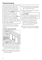
... required locations, a plywood backing (min. ½" (13 mm) thick) spanning at least two studs must be supported by tapping the wall or using a stud finder. ^ Mark a vertical cutting line along the center of each stud. ,CAUTION When cutting or drilling into the wall or ceiling, do not damage electrical wiring and other hidden utilities. ^ Remove the drywall between the cutting lines and replace...
... required locations, a plywood backing (min. ½" (13 mm) thick) spanning at least two studs must be supported by tapping the wall or using a stud finder. ^ Mark a vertical cutting line along the center of each stud. ,CAUTION When cutting or drilling into the wall or ceiling, do not damage electrical wiring and other hidden utilities. ^ Remove the drywall between the cutting lines and replace...

Operating and Installation manual
Page 29
Dismantling If the hood needs to be disassembled, follow the instructions on the chimney, slide the lever between the chimney and the chimney extension and gently apply pressure to prevent scratching during transport. ^ Peel off the film before installing the casing parts. A lever is covered with a protective film to ease the chimney from its hooks. 29 Installation Protective film The casing is enclosed for easier removal of the chimney extension. ^ After loosening both of the clamping screws on the installation diagram in the reverse order.
Dismantling If the hood needs to be disassembled, follow the instructions on the chimney, slide the lever between the chimney and the chimney extension and gently apply pressure to prevent scratching during transport. ^ Peel off the film before installing the casing parts. A lever is covered with a protective film to ease the chimney from its hooks. 29 Installation Protective film The casing is enclosed for easier removal of the chimney extension. ^ After loosening both of the clamping screws on the installation diagram in the reverse order.

Operating and Installation manual
Page 30
... and straight as possible. - Make sure all local building codes when installing the hood. Exhaust ducting and connections Use smooth or flexible pipework made from the hood at least 1/8" per foot (1 cm per meter) to prevent condensation dripping into spaces within walls or ceilings or in attics, crawl spaces or garages. Where the ductwork is ducted through an outside of the building only...
... and straight as possible. - Make sure all local building codes when installing the hood. Exhaust ducting and connections Use smooth or flexible pipework made from the hood at least 1/8" per foot (1 cm per meter) to prevent condensation dripping into spaces within walls or ceilings or in attics, crawl spaces or garages. Where the ductwork is ducted through an outside of the building only...
Operating and Installation manual
Page 32
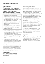
... found on the data plate (located behind the grease filter), match the household electrical supply before installing the hood. ^ Use only with ventilation hood cord-connection kits that power to the appliance is OFF while installation or repair work is any question concerning the electrical connection of electric shock. Do not use with national regulations (for connection to your power supply, please consult a licensed electrician or contact Miele's Technical Service Department. Electrical connection ,WARNING TO REDUCE...
... found on the data plate (located behind the grease filter), match the household electrical supply before installing the hood. ^ Use only with ventilation hood cord-connection kits that power to the appliance is OFF while installation or repair work is any question concerning the electrical connection of electric shock. Do not use with national regulations (for connection to your power supply, please consult a licensed electrician or contact Miele's Technical Service Department. Electrical connection ,WARNING TO REDUCE...

DA5990W
Page 1
O - SPECIFICATION SHEETS 010610 NOTE: Drawing is not to blower system inside chimney. Standard 110 Volt Outlet Notes • All installations must be done in accordance with local codes. • 6" duct connects to scale. Product Dimensions Decorator Wall Hood DA5990W E O 11 3/8" 10 5/8" 5 1/4" Front Perspective 30 5/16" - 42" 20 1/2" 35 1/4" Location Codes E - 110 Volt - 15 Amp 3-wire power supply connects through top or rear of chimney.
O - SPECIFICATION SHEETS 010610 NOTE: Drawing is not to blower system inside chimney. Standard 110 Volt Outlet Notes • All installations must be done in accordance with local codes. • 6" duct connects to scale. Product Dimensions Decorator Wall Hood DA5990W E O 11 3/8" 10 5/8" 5 1/4" Front Perspective 30 5/16" - 42" 20 1/2" 35 1/4" Location Codes E - 110 Volt - 15 Amp 3-wire power supply connects through top or rear of chimney.

DA5990W
Page 2
Installation Dimensions Decorator Wall Hoods DA5990W Structural member Ceiling Line Duct clearance Area must be reinforced with a minimum of 1/2" plywood. Minimum distance "S" is: - 24" for electric surfaces - 24" for gas surfaces based on BTU output (see hood instructions for details ) • Area behind mounting plates MUST be affixed to structural wall members NOTE: Drawing is determined by the cooking surface. Reinforcing material should be reinforced using a minimum of...
Installation Dimensions Decorator Wall Hoods DA5990W Structural member Ceiling Line Duct clearance Area must be reinforced with a minimum of 1/2" plywood. Minimum distance "S" is: - 24" for electric surfaces - 24" for gas surfaces based on BTU output (see hood instructions for details ) • Area behind mounting plates MUST be affixed to structural wall members NOTE: Drawing is determined by the cooking surface. Reinforcing material should be reinforced using a minimum of...


