Operating and Installation manual
Page 3
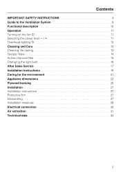
... SAFETY INSTRUCTIONS 4 Guide to the Ventilation System 8 Functional description 10 Operation 11 Turning on the fan s 11 Selecting the power level 11 Overhead lighting I 12 Cleaning and Care 13 Cleaning the casing 13 Grease filters 14 Active charcoal filter 15 Changing the light bulb 16 After Sales Service 17 Installation instructions 19 Caring for the environment 21 Appliance dimensions 22 Plywood backing 26 Installation 27 Installation instructions 27 Protective film 27 Dismantling 27 Installation materials 28 Electrical connection 30 Air extraction...
... SAFETY INSTRUCTIONS 4 Guide to the Ventilation System 8 Functional description 10 Operation 11 Turning on the fan s 11 Selecting the power level 11 Overhead lighting I 12 Cleaning and Care 13 Cleaning the casing 13 Grease filters 14 Active charcoal filter 15 Changing the light bulb 16 After Sales Service 17 Installation instructions 19 Caring for the environment 21 Appliance dimensions 22 Plywood backing 26 Installation 27 Installation instructions 27 Protective film 27 Dismantling 27 Installation materials 28 Electrical connection 30 Air extraction...
Operating and Installation manual
Page 4
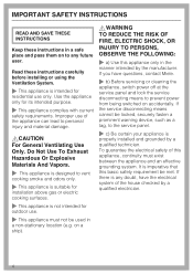
... doubt, have questions, contact Miele. ~ b) Before servicing or cleaning the appliance, switch power off at the service panel and lock the service disconnecting means to personal injury and material damage. ,CAUTION For General Ventilating Use Only. IMPORTANT SAFETY INSTRUCTIONS READ AND SAVE THESE INSTRUCTIONS Keep these instructions carefully before installing or using the Ventilation System. ~ This appliance is intended for residential use only. Read these instructions in a non-stationary...
... doubt, have questions, contact Miele. ~ b) Before servicing or cleaning the appliance, switch power off at the service panel and lock the service disconnecting means to personal injury and material damage. ,CAUTION For General Ventilating Use Only. IMPORTANT SAFETY INSTRUCTIONS READ AND SAVE THESE INSTRUCTIONS Keep these instructions carefully before installing or using the Ventilation System. ~ This appliance is intended for residential use only. Read these instructions in a non-stationary...
Operating and Installation manual
Page 5
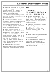
... other work and repairs should only be drawn up into the hood by a qualified technician in the "Cleaning and care" section of the cooking area. ~ e) Do not flambé or grill with electrical connections or components and mechanical parts is highly dangerous to the user and can cause operation faults. ~ g) Before discarding an old appliance, disconnect it from the power supply and remove the power cord to...
... other work and repairs should only be drawn up into the hood by a qualified technician in the "Cleaning and care" section of the cooking area. ~ e) Do not flambé or grill with electrical connections or components and mechanical parts is highly dangerous to the user and can cause operation faults. ~ g) Before discarding an old appliance, disconnect it from the power supply and remove the power cord to...

Operating and Installation manual
Page 6
... extend beneath the cookware. Supervise its controls. You may be damaged due to excessive heat from condensation. ~ Never operate gas burners without the grease filters in place. ~ Do not use a steam cleaner to clean the hood. when using the cooktop to prevent damage from the burners and the cookware. ~ Do not use the hood without cookware. Turn the burner off the burner. Adjust...
... extend beneath the cookware. Supervise its controls. You may be damaged due to excessive heat from condensation. ~ Never operate gas burners without the grease filters in place. ~ Do not use a steam cleaner to clean the hood. when using the cooktop to prevent damage from the burners and the cookware. ~ Do not use the hood without cookware. Turn the burner off the burner. Adjust...
Operating and Installation manual
Page 7
... FOLLOWING: ~ a) Installation work and electrical wiring must be done by qualified person(s) in the "Appliance dimensions" section of this hood with all applicable codes and standards, including fire-rated construction. ~ b) Sufficient air is needed for combustion and exhausting of gases through the flue (chimney of fuel burning equipment to prevent back drafting. Extension cords do not damage electrical wiring and other hidden utilities. ~ d) Ducted hoods must always be vented to the...
... FOLLOWING: ~ a) Installation work and electrical wiring must be done by qualified person(s) in the "Appliance dimensions" section of this hood with all applicable codes and standards, including fire-rated construction. ~ b) Sufficient air is needed for combustion and exhausting of gases through the flue (chimney of fuel burning equipment to prevent back drafting. Extension cords do not damage electrical wiring and other hidden utilities. ~ d) Ducted hoods must always be vented to the...

Operating and Installation manual
Page 10
... when the hood is then recirculated back into the kitchen through the grease filters and an active charcoal filter. The recirculation mode requires an install kit and charcoal filter which are optional accessories. Before using the hood in recirculation mode, ensure that no exchange of the exhaust fan automatically opens the flap blowing the inside air and cooking odors outside air and room air can occur. When the hood is in and cleaned by the grease filters and directed outside.
... when the hood is then recirculated back into the kitchen through the grease filters and an active charcoal filter. The recirculation mode requires an install kit and charcoal filter which are optional accessories. Before using the hood in recirculation mode, ensure that no exchange of the exhaust fan automatically opens the flap blowing the inside air and cooking odors outside air and room air can occur. When the hood is in and cleaned by the grease filters and directed outside.
Operating and Installation manual
Page 13
.... Special instructions for cleaning "Stainless steel" surfaces and "Stainless steel colored controls" should be applied. These will damage the surface. ,The halogen bulbs are very hot when in use too much water when cleaning the controls. Never use a stainless steel cleaner on the hood. This can be followed in the kitchen. Do not use abrasive cleaners, scouring pads, steel wool or caustic (oven) cleaners on these controls. 13 It is halogen lighting in...
.... Special instructions for cleaning "Stainless steel" surfaces and "Stainless steel colored controls" should be applied. These will damage the surface. ,The halogen bulbs are very hot when in use too much water when cleaning the controls. Never use a stainless steel cleaner on the hood. This can be followed in the kitchen. Do not use abrasive cleaners, scouring pads, steel wool or caustic (oven) cleaners on these controls. 13 It is halogen lighting in...
Operating and Installation manual
Page 14
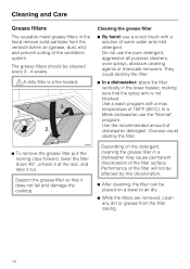
... air dry. ^ While the filters are removed, clean any dirt or grease from the vented kitchen air (grease, dust, etc) and prevent soiling of the filter surface. The grease filters should be placed on the detergent, cleaning the grease filter in a dishwasher may cause permanent discoloration of the ventilation system. Cleaning the grease filter ^ By hand: use a scrub brush with a max. Use the recommended amount of 150°F (65°C). Support the grease filter...
... air dry. ^ While the filters are removed, clean any dirt or grease from the vented kitchen air (grease, dust, etc) and prevent soiling of the filter surface. The grease filters should be placed on the detergent, cleaning the grease filter in a dishwasher may cause permanent discoloration of the ventilation system. Cleaning the grease filter ^ By hand: use a scrub brush with a max. Use the recommended amount of 150°F (65°C). Support the grease filter...
Operating and Installation manual
Page 15
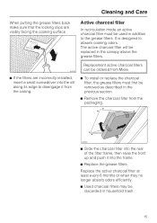
.... ^ Remove the charcoal filter from Miele. ^ If the filters are incorrectly installed, insert a small screwdriver into the frame. ^ Replace the grease filters. The active charcoal filter will be discarded in household trash. 15 It is designed to disengage it into the slit along its edge to absorb cooking odors. Replace the active charcoal filter at least every 6 months or when they no longer absorb odors efficiently. ^ Used charcoal filters may...
.... ^ Remove the charcoal filter from Miele. ^ If the filters are incorrectly installed, insert a small screwdriver into the frame. ^ Replace the grease filters. The active charcoal filter will be discarded in household trash. 15 It is designed to disengage it into the slit along its edge to absorb cooking odors. Replace the active charcoal filter at least every 6 months or when they no longer absorb odors efficiently. ^ Used charcoal filters may...

Operating and Installation manual
Page 16
... reverse order. ^ Replace the grease filters. 16 Do not attempt to change the bulbs until they have had sufficient time to cool. Follow the bulb manufacturer's instructions. ^ Remove the grease filters. ^ Turn the knurled screw counterclockwise. Cleaning and Care Changing the light bulb ,WARNING TO REDUCE THE RISK OF FIRE, ELECTRIC SHOCK, OR INJURY TO PERSONS, OBSERVE THE FOLLOWING: Before changing the light bulbs, disconnect the hood from the power supply, see "Important...
... reverse order. ^ Replace the grease filters. 16 Do not attempt to change the bulbs until they have had sufficient time to cool. Follow the bulb manufacturer's instructions. ^ Remove the grease filters. ^ Turn the knurled screw counterclockwise. Cleaning and Care Changing the light bulb ,WARNING TO REDUCE THE RISK OF FIRE, ELECTRIC SHOCK, OR INJURY TO PERSONS, OBSERVE THE FOLLOWING: Before changing the light bulbs, disconnect the hood from the power supply, see "Important...

Operating and Installation manual
Page 23
Wall/ceiling area respectively for air extraction mode 6" (150 mm), with reducing collar 5" (125 mm). Connection for vent hole and outlet installation. For recirculation mode only the outlet installation is required. a Ar extraction mode b Recirculation mode c Recirculation vent positioned at the top (recirculation mode only) d, e Installation area; Appliance dimensions 23 For recirculation mode only d.
Wall/ceiling area respectively for air extraction mode 6" (150 mm), with reducing collar 5" (125 mm). Connection for vent hole and outlet installation. For recirculation mode only the outlet installation is required. a Ar extraction mode b Recirculation mode c Recirculation vent positioned at the top (recirculation mode only) d, e Installation area; Appliance dimensions 23 For recirculation mode only d.
Operating and Installation manual
Page 24
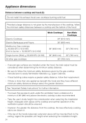
...) above the electric cooktop is also recommended. - If several gas surfaces are drawn in. - If local building codes require a greater safety distance, follow the minimum safety distances between cooktop and hood (S) Do not install this exhaust hood over cooktops burning solid fuel. See "Important Safety Instructions" for further information. - Appliance dimensions Distance between a cooktop and the bottom of the hood: Electric Cooktops Electric Barbeques and Fryers Multiburner Gas cooktops < 43...
...) above the electric cooktop is also recommended. - If several gas surfaces are drawn in. - If local building codes require a greater safety distance, follow the minimum safety distances between cooktop and hood (S) Do not install this exhaust hood over cooktops burning solid fuel. See "Important Safety Instructions" for further information. - Appliance dimensions Distance between a cooktop and the bottom of the hood: Electric Cooktops Electric Barbeques and Fryers Multiburner Gas cooktops < 43...

Operating and Installation manual
Page 25
Drilling diagram Appliance dimensions To prepare a backing plate, the spacings for the 5 mm screws need to be mounted directly to the wall, follow the additional instructions given in the included "Installation diagram". 25 If the ventilation hood will be drilled as possible. It should be installed as low as shown. * The dimension between the ceiling and the middle bracket may vary depending on the position of the vent cut-out and the power socket.
Drilling diagram Appliance dimensions To prepare a backing plate, the spacings for the 5 mm screws need to be mounted directly to the wall, follow the additional instructions given in the included "Installation diagram". 25 If the ventilation hood will be drilled as possible. It should be installed as low as shown. * The dimension between the ceiling and the middle bracket may vary depending on the position of the vent cut-out and the power socket.
Operating and Installation manual
Page 26
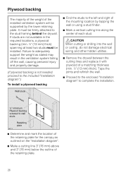
... "Installation diagram". ^ Make a cutting line 3" (76 mm) above and 3" (76 mm) below the outline of the retaining plate. 26 Plywood backing The majority of the weight of the installed ventilation system will be supported by tapping the wall or using a stud finder. ^ Mark a vertical cutting line along the center of each stud. ,CAUTION When cutting or drilling into the wall or ceiling, do not damage electrical wiring...
... "Installation diagram". ^ Make a cutting line 3" (76 mm) above and 3" (76 mm) below the outline of the retaining plate. 26 Plywood backing The majority of the weight of the installed ventilation system will be supported by tapping the wall or using a stud finder. ^ Mark a vertical cutting line along the center of each stud. ,CAUTION When cutting or drilling into the wall or ceiling, do not damage electrical wiring...
Operating and Installation manual
Page 27
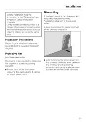
... a danger of the chimney extension. Protective film (stainless steel units) The casing is covered with a protective film to ease the chimney from the chimney, slide the lever between the chimney and the chimney extension and gently apply pressure to prevent scratching during transport. ^ Please peel off the film before installing the casing parts. Installation Before installation read the information in the included Installation diagram. It can be...
... a danger of the chimney extension. Protective film (stainless steel units) The casing is covered with a protective film to ease the chimney from the chimney, slide the lever between the chimney and the chimney extension and gently apply pressure to prevent scratching during transport. ^ Please peel off the film before installing the casing parts. Installation Before installation read the information in the included Installation diagram. It can be...
Operating and Installation manual
Page 29
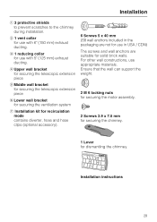
... walls. Installation instructions 29 d Upper wall bracket for securing the telescopic extension piece e Middle wall bracket for securing the telescopic extension piece f Lower wall bracket for securing the ventilation system g Installation kit for recirculation mode contains diverter, hose and hose clips (optional accessory). 6 Screws 5 x 40 mm (S8 wall anchors included in the packaging are not for use in USA / CDN) The screws and wall anchors are suitable for use with 6" (150 mm) exhaust ducting. b 1 vent...
... walls. Installation instructions 29 d Upper wall bracket for securing the telescopic extension piece e Middle wall bracket for securing the telescopic extension piece f Lower wall bracket for securing the ventilation system g Installation kit for recirculation mode contains diverter, hose and hose clips (optional accessory). 6 Screws 5 x 40 mm (S8 wall anchors included in the packaging are not for use in USA / CDN) The screws and wall anchors are suitable for use with 6" (150 mm) exhaust ducting. b 1 vent...

Operating and Installation manual
Page 30
... data plate (located behind the grease filters), match the household electrical supply before installing the hood. ^ Use only with this appliance to a 120 V, 60 Hz, 15 A power outlet. Do not use with ventilation hood cord-connection kits that the voltage, load and circuit rating information found acceptable for connection to your power supply, please consult a licensed electrician or contact Miele's Technical Service Department. Important The hood comes equipped with a 4 ft (1.2 m) power cord with...
... data plate (located behind the grease filters), match the household electrical supply before installing the hood. ^ Use only with this appliance to a 120 V, 60 Hz, 15 A power outlet. Do not use with ventilation hood cord-connection kits that the voltage, load and circuit rating information found acceptable for connection to your power supply, please consult a licensed electrician or contact Miele's Technical Service Department. Important The hood comes equipped with a 4 ft (1.2 m) power cord with...

Operating and Installation manual
Page 31
... ventilation exhaust. - Do not vent exhaust air into the appliance. - Please read and follow the "IMPORTANT SAFETY INSTRUCTIONS" to properly exhaust air, the exhaust gases extracted by the hood should not be harmful or fatal if inhaled. Exhaust ducting and connections Use smooth or flexible pipework made from the hood at least 1/8" per foot (1 cm per meter) to prevent condensation dripping into spaces within walls or ceilings...
... ventilation exhaust. - Do not vent exhaust air into the appliance. - Please read and follow the "IMPORTANT SAFETY INSTRUCTIONS" to properly exhaust air, the exhaust gases extracted by the hood should not be harmful or fatal if inhaled. Exhaust ducting and connections Use smooth or flexible pipework made from the hood at least 1/8" per foot (1 cm per meter) to prevent condensation dripping into spaces within walls or ceilings...
DA399-5 Décor Wall Hood
Page 1
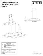
O - Product Dimensions Decorator Wall Hood DA399-5 E O 11 7/16" 10 5/8" 4 3/4" Front Perspective 28 5/16" - 40" See Notes 20 1/2" 35 7/16" Location Codes E - 110 Volt - 15 Amp 3-wire power supply connects through top or rear of chimney. SPECIFICATION SHEETS 021111 Standard 110 Volt Oultlet Notes • All installations must be done in accordance with local codes. • Recirculation: 32 11/16" - 45 1/4" • 6" duct connects to scale. NOTE: Drawing is not to blower system inside chimney.
O - Product Dimensions Decorator Wall Hood DA399-5 E O 11 7/16" 10 5/8" 4 3/4" Front Perspective 28 5/16" - 40" See Notes 20 1/2" 35 7/16" Location Codes E - 110 Volt - 15 Amp 3-wire power supply connects through top or rear of chimney. SPECIFICATION SHEETS 021111 Standard 110 Volt Oultlet Notes • All installations must be done in accordance with local codes. • Recirculation: 32 11/16" - 45 1/4" • 6" duct connects to scale. NOTE: Drawing is not to blower system inside chimney.
DA399-5 Décor Wall Hood
Page 2
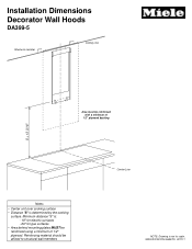
SPECIFICATION SHEETS 021111 Installation Dimensions Decorator Wall Hoods DA399-5 Structural member Ceiling Line Area must be affixed to structural wall members Center Line NOTE: Drawing is not to scale. Reinforcing material should be reinforced with a minimum of 1/2" plywood backing S + 13 3/16" Notes • Center unit over cooking surface • Distance "S" is : - 18" for electric surfaces - 26" for gas surfaces • Area behind mounting plates MUST be reinforced using a minimum of 1/2" plywood. Minimum distance "S" is determined by the cooking surface.
SPECIFICATION SHEETS 021111 Installation Dimensions Decorator Wall Hoods DA399-5 Structural member Ceiling Line Area must be affixed to structural wall members Center Line NOTE: Drawing is not to scale. Reinforcing material should be reinforced with a minimum of 1/2" plywood backing S + 13 3/16" Notes • Center unit over cooking surface • Distance "S" is : - 18" for electric surfaces - 26" for gas surfaces • Area behind mounting plates MUST be reinforced using a minimum of 1/2" plywood. Minimum distance "S" is determined by the cooking surface.


