Operating and Installation manual
Page 3
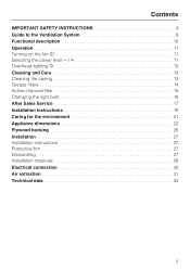
... SAFETY INSTRUCTIONS 4 Guide to the Ventilation System 8 Functional description 10 Operation 11 Turning on the fan s 11 Selecting the power level 11 Overhead lighting I 12 Cleaning and Care 13 Cleaning the casing 13 Grease filters 14 Active charcoal filter 15 Changing the light bulb 16 After Sales Service 17 Installation instructions 19 Caring for the environment 21 Appliance dimensions 22 Plywood backing 26 Installation 27 Installation instructions 27 Protective film 27 Dismantling 27 Installation materials 28 Electrical connection 30 Air extraction...
... SAFETY INSTRUCTIONS 4 Guide to the Ventilation System 8 Functional description 10 Operation 11 Turning on the fan s 11 Selecting the power level 11 Overhead lighting I 12 Cleaning and Care 13 Cleaning the casing 13 Grease filters 14 Active charcoal filter 15 Changing the light bulb 16 After Sales Service 17 Installation instructions 19 Caring for the environment 21 Appliance dimensions 22 Plywood backing 26 Installation 27 Installation instructions 27 Protective film 27 Dismantling 27 Installation materials 28 Electrical connection 30 Air extraction...
Operating and Installation manual
Page 4
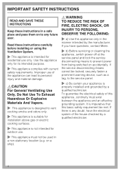
... requirements. If the service disconnecting means cannot be met. Improper use of the house checked by the manufacturer. If you have questions, contact Miele. ~ b) Before servicing or cleaning the appliance, switch power off at the service panel and lock the service disconnecting means to vent cooking smoke and odors only. ~ This appliance is suitable for installation above gas or electric cooking surfaces. ~ This appliance is any future user...
... requirements. If the service disconnecting means cannot be met. Improper use of the house checked by the manufacturer. If you have questions, contact Miele. ~ b) Before servicing or cleaning the appliance, switch power off at the service panel and lock the service disconnecting means to vent cooking smoke and odors only. ~ This appliance is suitable for installation above gas or electric cooking surfaces. ~ This appliance is any future user...
Operating and Installation manual
Page 5
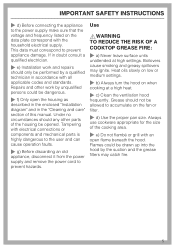
... the cooking area. ~ e) Do not flambé or grill with electrical connections or components and mechanical parts is highly dangerous to the user and can cause operation faults. ~ g) Before discarding an old appliance, disconnect it from the power supply and remove the power cord to prevent appliance damage. Use ,WARNING TO REDUCE THE RISK OF A COOKTOP GREASE FIRE: ~ a) Never leave surface units unattended at a high heat. ~ c) Clean the ventilation hood...
... the cooking area. ~ e) Do not flambé or grill with electrical connections or components and mechanical parts is highly dangerous to the user and can cause operation faults. ~ g) Before discarding an old appliance, disconnect it from the power supply and remove the power cord to prevent appliance damage. Use ,WARNING TO REDUCE THE RISK OF A COOKTOP GREASE FIRE: ~ a) Never leave surface units unattended at a high heat. ~ c) Clean the ventilation hood...

Operating and Installation manual
Page 6
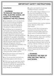
... the cookware. ~ Do not use a steam cleaner to clean the hood. Steam could penetrate electrical components and cause a short circuit. 6 IMPORTANT SAFETY INSTRUCTIONS ,WARNING TO REDUCE THE RISK OF INJURY TO PERSONS IN THE EVENT OF A COOKTOP GREASE FIRE, OBSERVE THE FOLLOWING*: ~ a) SMOTHER FLAMES with a close fitting lid, cookie sheet, or metal tray then turn on "Kitchen Firesafety Tips" published by...
... the cookware. ~ Do not use a steam cleaner to clean the hood. Steam could penetrate electrical components and cause a short circuit. 6 IMPORTANT SAFETY INSTRUCTIONS ,WARNING TO REDUCE THE RISK OF INJURY TO PERSONS IN THE EVENT OF A COOKTOP GREASE FIRE, OBSERVE THE FOLLOWING*: ~ a) SMOTHER FLAMES with a close fitting lid, cookie sheet, or metal tray then turn on "Kitchen Firesafety Tips" published by...
Operating and Installation manual
Page 7
...-state speed control device. ~ f) Do not use this hood with all applicable codes and standards, including fire-rated construction. ~ b) Sufficient air is needed for Heating, Refrigeration and Air Conditioning Engineers (ASHRAE), and the local code authorities. ~ c) When cutting or drilling into the wall or ceiling, do not guarantee the required safety of the appliance, (e.g. Extension cords do not damage electrical wiring and other hidden utilities. ~ d) Ducted hoods must always be vented...
...-state speed control device. ~ f) Do not use this hood with all applicable codes and standards, including fire-rated construction. ~ b) Sufficient air is needed for Heating, Refrigeration and Air Conditioning Engineers (ASHRAE), and the local code authorities. ~ c) When cutting or drilling into the wall or ceiling, do not guarantee the required safety of the appliance, (e.g. Extension cords do not damage electrical wiring and other hidden utilities. ~ d) Ducted hoods must always be vented...

Operating and Installation manual
Page 10
... active charcoal filter is in and cleaned by the grease filters and directed outside. Before using the hood in recirculation mode, ensure that no exchange of outside . The filtered air is then recirculated back into the kitchen through the grease filters and an active charcoal filter. Air is drawn through a vent at the top of the hood's chimney. The recirculation mode requires an install kit and charcoal filter which are optional accessories. When the hood is turned on, the air pressure of the exhaust fan...
... active charcoal filter is in and cleaned by the grease filters and directed outside. Before using the hood in recirculation mode, ensure that no exchange of outside . The filtered air is then recirculated back into the kitchen through the grease filters and an active charcoal filter. Air is drawn through a vent at the top of the hood's chimney. The recirculation mode requires an install kit and charcoal filter which are optional accessories. When the hood is turned on, the air pressure of the exhaust fan...
Operating and Installation manual
Page 13
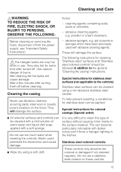
... (oven) cleaners on these controls. 13 Wet cleaning the hot bulbs will damage the surface. Special instructions for stainless steel surfaces (not applicable to the surface material. To help prevent resoiling, a conditioner for cleaning "Stainless steel" surfaces and "Stainless steel colored controls" should be cleaned with a mild solution of burns. It is halogen lighting in addition to the general "Cleaning the casing" instructions. Cleaning the casing The following instructions for stainless steel...
... (oven) cleaners on these controls. 13 Wet cleaning the hot bulbs will damage the surface. Special instructions for stainless steel surfaces (not applicable to the surface material. To help prevent resoiling, a conditioner for cleaning "Stainless steel" surfaces and "Stainless steel colored controls" should be cleaned with a mild solution of burns. It is halogen lighting in addition to the general "Cleaning the casing" instructions. Cleaning the casing The following instructions for stainless steel...
Operating and Installation manual
Page 14
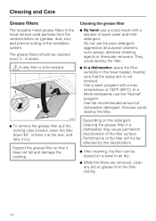
... discoloration of the ventilation system. Performance of 150°F (65°C). Cleaning the grease filter ^ By hand: use a scrub brush with a max. In a Miele dishwasher use the pure detergent, aggressive all purpose cleaners, oven sprays, abrasive cleaning agents or limescale removers. Use a wash program with a solution of dishwasher detergent. Cleaning and Care Grease filters The reusable metal grease filters in the hood remove solid particles from the filter casing. 14...
... discoloration of the ventilation system. Performance of 150°F (65°C). Cleaning the grease filter ^ By hand: use a scrub brush with a max. In a Miele dishwasher use the pure detergent, aggressive all purpose cleaners, oven sprays, abrasive cleaning agents or limescale removers. Use a wash program with a solution of dishwasher detergent. Cleaning and Care Grease filters The reusable metal grease filters in the hood remove solid particles from the filter casing. 14...
Operating and Installation manual
Page 15
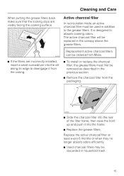
... efficiently. ^ Used charcoal filters may be replaced in the canopy above the grease filters. The active charcoal filter will be discarded in addition to absorb cooking odors. It is designed to the grease filters. Replacement active charcoal filters can be ordered from Miele. ^ If the filters are visibly facing the cooking surface Active charcoal filter In recirculation mode an active charcoal filter must first be removed as described in the previous section. ^ Remove the charcoal filter from the...
... efficiently. ^ Used charcoal filters may be replaced in the canopy above the grease filters. The active charcoal filter will be discarded in addition to absorb cooking odors. It is designed to the grease filters. Replacement active charcoal filters can be ordered from Miele. ^ If the filters are visibly facing the cooking surface Active charcoal filter In recirculation mode an active charcoal filter must first be removed as described in the previous section. ^ Remove the charcoal filter from the...

Operating and Installation manual
Page 16
Cleaning and Care Changing the light bulb ,WARNING TO REDUCE THE RISK OF FIRE, ELECTRIC SHOCK, OR INJURY TO PERSONS, OBSERVE THE FOLLOWING: Before changing the light bulbs, disconnect the hood from the power supply, see "Important Safety Instructions". Follow the bulb manufacturer's instructions. ^ Remove the grease filters. ^ Turn the knurled screw counterclockwise. When in the reverse order. ^ Replace the grease filters. 16 Do not touch the bulb surface. Fingerprints or body oils deposited...
Cleaning and Care Changing the light bulb ,WARNING TO REDUCE THE RISK OF FIRE, ELECTRIC SHOCK, OR INJURY TO PERSONS, OBSERVE THE FOLLOWING: Before changing the light bulbs, disconnect the hood from the power supply, see "Important Safety Instructions". Follow the bulb manufacturer's instructions. ^ Remove the grease filters. ^ Turn the knurled screw counterclockwise. When in the reverse order. ^ Replace the grease filters. 16 Do not touch the bulb surface. Fingerprints or body oils deposited...

Operating and Installation manual
Page 23
Appliance dimensions 23 For recirculation mode only the outlet installation is required. Connection for vent hole and outlet installation. Wall/ceiling area respectively for air extraction mode 6" (150 mm), with reducing collar 5" (125 mm). For recirculation mode only d. a Ar extraction mode b Recirculation mode c Recirculation vent positioned at the top (recirculation mode only) d, e Installation area;
Appliance dimensions 23 For recirculation mode only the outlet installation is required. Connection for vent hole and outlet installation. Wall/ceiling area respectively for air extraction mode 6" (150 mm), with reducing collar 5" (125 mm). For recirculation mode only d. a Ar extraction mode b Recirculation mode c Recirculation vent positioned at the top (recirculation mode only) d, e Installation area;
Operating and Installation manual
Page 24
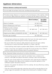
... cooktops burning solid fuel. Take the user's body height into consideration when selecting the installation height. Appliance dimensions Distance between a cooktop and the bottom of the hoods telescopic extension piece will be mounted flush to easily flammable materials e.g. Provided a larger distance is not given by the gas cooktop manufacturer to the ceiling, regard the possible unit height when selecting the installation height. 24 upper cabinets. - See "Important Safety Instructions...
... cooktops burning solid fuel. Take the user's body height into consideration when selecting the installation height. Appliance dimensions Distance between a cooktop and the bottom of the hoods telescopic extension piece will be mounted flush to easily flammable materials e.g. Provided a larger distance is not given by the gas cooktop manufacturer to the ceiling, regard the possible unit height when selecting the installation height. 24 upper cabinets. - See "Important Safety Instructions...

Operating and Installation manual
Page 25
If the ventilation hood will be mounted directly to be installed as low as shown. * The dimension between the ceiling and the middle bracket may vary depending on the position of the vent cut-out and the power socket. Drilling diagram Appliance dimensions To prepare a backing plate, the spacings for the 5 mm screws need to the wall, follow the additional instructions given in the included "Installation diagram". 25 It should be drilled as possible.
If the ventilation hood will be mounted directly to be installed as low as shown. * The dimension between the ceiling and the middle bracket may vary depending on the position of the vent cut-out and the power socket. Drilling diagram Appliance dimensions To prepare a backing plate, the spacings for the 5 mm screws need to the wall, follow the additional instructions given in the included "Installation diagram". 25 It should be drilled as possible.
Operating and Installation manual
Page 26
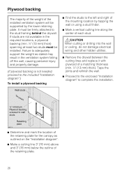
... required locations, a plywood backing (min. ½" (13 mm) thick) spanning at least two studs must be supported by tapping the wall or using a stud finder. ^ Mark a vertical cutting line along the center of each stud. ,CAUTION When cutting or drilling into the wall or ceiling, do not damage electrical wiring and other hidden utilities. ^ Remove the drywall between the cutting lines and replace...
... required locations, a plywood backing (min. ½" (13 mm) thick) spanning at least two studs must be supported by tapping the wall or using a stud finder. ^ Mark a vertical cutting line along the center of each stud. ,CAUTION When cutting or drilling into the wall or ceiling, do not damage electrical wiring and other hidden utilities. ^ Remove the drywall between the cutting lines and replace...
Operating and Installation manual
Page 27
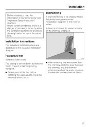
... poisonous fumes by when the ventilation system and a furnace drawing interior air run at the same time. Installation Before installation read the information in the included Installation diagram. Protective film (stainless steel units) The casing is covered with a protective film to be removed without tools. ^ After removing the two screws from the chimney, slide the lever between the chimney and the chimney extension and gently apply pressure...
... poisonous fumes by when the ventilation system and a furnace drawing interior air run at the same time. Installation Before installation read the information in the included Installation diagram. Protective film (stainless steel units) The casing is covered with a protective film to be removed without tools. ^ After removing the two screws from the chimney, slide the lever between the chimney and the chimney extension and gently apply pressure...
Operating and Installation manual
Page 29
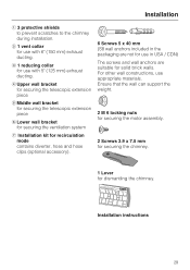
... telescopic extension piece f Lower wall bracket for securing the ventilation system g Installation kit for recirculation mode contains diverter, hose and hose clips (optional accessory). 6 Screws 5 x 40 mm (S8 wall anchors included in USA / CDN) The screws and wall anchors are not for solid brick walls. Installation instructions 29 b 1 vent collar for use in the packaging are suitable for use with 5" (125 mm) exhaust ducting. Ensure that the wall can support the weight. 2 M 6 locking...
... telescopic extension piece f Lower wall bracket for securing the ventilation system g Installation kit for recirculation mode contains diverter, hose and hose clips (optional accessory). 6 Screws 5 x 40 mm (S8 wall anchors included in USA / CDN) The screws and wall anchors are not for solid brick walls. Installation instructions 29 b 1 vent collar for use in the packaging are suitable for use with 5" (125 mm) exhaust ducting. Ensure that the wall can support the weight. 2 M 6 locking...

Operating and Installation manual
Page 30
... while installation or repair work is performed. ^ Verify that the voltage, load and circuit rating information found acceptable for use an extension cord. U 1-800-999-1360 V 1-800-565-6435 Grounding Instructions This appliance must be plugged into an outlet that have been investigated and found on the data plate (located behind the grease filters), match the household electrical supply before installing the hood. ^ Use only with ventilation hood cord-connection kits...
... while installation or repair work is performed. ^ Verify that the voltage, load and circuit rating information found acceptable for use an extension cord. U 1-800-999-1360 V 1-800-565-6435 Grounding Instructions This appliance must be plugged into an outlet that have been investigated and found on the data plate (located behind the grease filters), match the household electrical supply before installing the hood. ^ Use only with ventilation hood cord-connection kits...

Operating and Installation manual
Page 31
.... Make sure all local building codes when installing the hood. To reduce the risk of personal injury. The ducting should be vented outside wall, a Telescopic Wall Vent can be bent or compressed. - The exhaust duct must not be as short and straight as possible. - Follow all connections are secure. - Where the ductwork is used . 31 To achieve the most efficient air extraction and quietest noise levels, consider...
.... Make sure all local building codes when installing the hood. To reduce the risk of personal injury. The ducting should be vented outside wall, a Telescopic Wall Vent can be bent or compressed. - The exhaust duct must not be as short and straight as possible. - Follow all connections are secure. - Where the ductwork is used . 31 To achieve the most efficient air extraction and quietest noise levels, consider...
DA398-5 Décor Wall Hood
Page 1
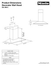
Product Dimensions Decorator Wall Hood DA 398-5 E O 11 7/16" 10 5/8" 4 3/4" Front Perspective 28 5/16" - 40" See Notes 20 1/2" 29 7/16" Location Codes E - 110 Volt - 15 Amp 3-wire power supply connects through top or rear of chimney. O - SPECIFICATION SHEETS 021111 NOTE: Drawing is not to blower system inside chimney. Standard 110 Volt Oultlet Notes • All installations must be done in accordance with local codes. • Recirculation: 32 11/16" - 45 1/4" • 6" duct connects to scale.
Product Dimensions Decorator Wall Hood DA 398-5 E O 11 7/16" 10 5/8" 4 3/4" Front Perspective 28 5/16" - 40" See Notes 20 1/2" 29 7/16" Location Codes E - 110 Volt - 15 Amp 3-wire power supply connects through top or rear of chimney. O - SPECIFICATION SHEETS 021111 NOTE: Drawing is not to blower system inside chimney. Standard 110 Volt Oultlet Notes • All installations must be done in accordance with local codes. • Recirculation: 32 11/16" - 45 1/4" • 6" duct connects to scale.
DA398-5 Décor Wall Hood
Page 2
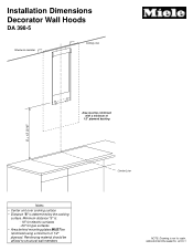
SPECIFICATION SHEETS 021111 Installation Dimensions Decorator Wall Hoods DA 398-5 Structural member Ceiling Line Area must be affixed to structural wall members Center Line NOTE: Drawing is not to scale. Reinforcing material should be reinforced with a minimum of 1/2" plywood backing S + 13 3/16" Notes • Center unit over cooking surface • Distance "S" is : - 18" for electric surfaces - 26" for gas surfaces • Area behind mounting plates MUST be reinforced using a minimum of 1/2" plywood. Minimum distance "S" is determined by the cooking surface.
SPECIFICATION SHEETS 021111 Installation Dimensions Decorator Wall Hoods DA 398-5 Structural member Ceiling Line Area must be affixed to structural wall members Center Line NOTE: Drawing is not to scale. Reinforcing material should be reinforced with a minimum of 1/2" plywood backing S + 13 3/16" Notes • Center unit over cooking surface • Distance "S" is : - 18" for electric surfaces - 26" for gas surfaces • Area behind mounting plates MUST be reinforced using a minimum of 1/2" plywood. Minimum distance "S" is determined by the cooking surface.


