Operating and Installation manual
Page 1
en - US, CA M.-Nr. 09 190 990 Operating and Installation Instructions Ventilation System DA 3460 DA 3480 DA 3490 To prevent accidents and appliance damage, read these instructions before installation or use.
en - US, CA M.-Nr. 09 190 990 Operating and Installation Instructions Ventilation System DA 3460 DA 3480 DA 3490 To prevent accidents and appliance damage, read these instructions before installation or use.
Operating and Installation manual
Page 2
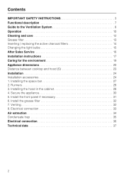
... 13 Inserting / replacing the active charcoal filters 14 Changing the light bulbs 15 After Sales Service 16 Installation instructions 17 Caring for the environment 19 Appliance dimensions 20 Distance between cooktop and hood (S 23 Installation 24 Installation accessories 24 1. Runners 28 3. Secure the appliance 30 5. Electrical connection 33 Air extraction 34 Condensate trap...
... 13 Inserting / replacing the active charcoal filters 14 Changing the light bulbs 15 After Sales Service 16 Installation instructions 17 Caring for the environment 19 Appliance dimensions 20 Distance between cooktop and hood (S 23 Installation 24 Installation accessories 24 1. Runners 28 3. Secure the appliance 30 5. Electrical connection 33 Air extraction 34 Condensate trap...

Operating and Installation manual
Page 3
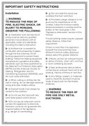
... Exhaust Hazardous Or Explosive Materials And Vapors. ~ This appliance is designed to vent cooking smoke and odors only. ~ This appliance is suitable for installation above gas or electric cooking surfaces. ~ This appliance is not intended for outdoor use of the appliance can lead to the service panel. ~... c) Be certain your appliance is any doubt, have questions, contact Miele. ~ b) Before servicing or cleaning the appliance, switch power off at the service panel and lock the service disconnecting means to any future user...
... Exhaust Hazardous Or Explosive Materials And Vapors. ~ This appliance is designed to vent cooking smoke and odors only. ~ This appliance is suitable for installation above gas or electric cooking surfaces. ~ This appliance is not intended for outdoor use of the appliance can lead to the service panel. ~... c) Be certain your appliance is any doubt, have questions, contact Miele. ~ b) Before servicing or cleaning the appliance, switch power off at the service panel and lock the service disconnecting means to any future user...

Operating and Installation manual
Page 4
...should only be performed by the suction and the grease filters may ignite. If in doubt consult a qualified electrician. ~ e) Installation work and repairs should any other work by unqualified persons could be dangerous. ~ f) Only open flame beneath the hood. ...hood on the data plate correspond with all applicable codes and standards. Tampering with an open the housing as described in the enclosed "Installation diagram" and in accordance with the household electrical supply. Boilovers cause smoking and greasy spillovers may catch fire. 4 IMPORTANT SAFETY INSTRUCTIONS...
...should only be performed by the suction and the grease filters may ignite. If in doubt consult a qualified electrician. ~ e) Installation work and repairs should any other work by unqualified persons could be dangerous. ~ f) Only open flame beneath the hood. ...hood on the data plate correspond with all applicable codes and standards. Tampering with an open the housing as described in the enclosed "Installation diagram" and in accordance with the household electrical supply. Boilovers cause smoking and greasy spillovers may catch fire. 4 IMPORTANT SAFETY INSTRUCTIONS...
Operating and Installation manual
Page 6
... the American Society for combustion and exhausting of gases through the flue (chimney of the appliance, (e.g. danger of overheating). ~ g) Do not install this hood over cooktops that burn solid fuel. ~ h) Provided a larger distance is more than one appliance beneath the hood and they have...advice before connecting an exhaust hood vent to an existing, inactive chimney or vent flue. ~ k) Any fittings, sealant, or materials used to install the ductwork must always be made of this hood with all applicable codes and standards, including fire-rated construction. ~ b) Sufficient air is needed...
... the American Society for combustion and exhausting of gases through the flue (chimney of the appliance, (e.g. danger of overheating). ~ g) Do not install this hood over cooktops that burn solid fuel. ~ h) Provided a larger distance is more than one appliance beneath the hood and they have...advice before connecting an exhaust hood vent to an existing, inactive chimney or vent flue. ~ k) Any fittings, sealant, or materials used to install the ductwork must always be made of this hood with all applicable codes and standards, including fire-rated construction. ~ b) Sufficient air is needed...
Operating and Installation manual
Page 7
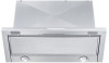
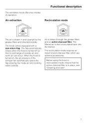
The recirculation mode requires an install kit and charcoal filter which are optional accessories. The filtered air is drawn in and cleaned by the grease filters and directed outside. Functional description ...
The recirculation mode requires an install kit and charcoal filter which are optional accessories. The filtered air is drawn in and cleaned by the grease filters and directed outside. Functional description ...
Operating and Installation manual
Page 16
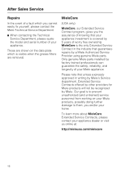
...Miele parts installed by Miele. To learn more about MieleCare Extended Service Contracts, please contact your appliance. Please note that unless expressly approved in the industry that your home. MieleCare (USA only) MieleCare, our Extended Service Contract program, gives you and/or your appliance investment is covered by a Miele Authorized Service Provider using genuine Miele... from working on the data plate which you cannot easily fix yourself, please contact the Miele Technical Service Department. ^ When contacting the Technical Service Department, please quote the model and...
...Miele parts installed by Miele. To learn more about MieleCare Extended Service Contracts, please contact your appliance. Please note that unless expressly approved in the industry that your home. MieleCare (USA only) MieleCare, our Extended Service Contract program, gives you and/or your appliance investment is covered by a Miele Authorized Service Provider using genuine Miele... from working on the data plate which you cannot easily fix yourself, please contact the Miele Technical Service Department. ^ When contacting the Technical Service Department, please quote the model and...

Operating and Installation manual
Page 17
Leave these instructions and the "Important Safety Instructions" before installing this ventilation system. Please refer to our website to change. Installation Instructions Read these instructions with the appliance for the consumer/user. Information is subject to obtain the most current product specification, technical & warranty information. The installation steps are described in the enclosed "Installation Diagram".
Leave these instructions and the "Important Safety Instructions" before installing this ventilation system. Please refer to our website to change. Installation Instructions Read these instructions with the appliance for the consumer/user. Information is subject to obtain the most current product specification, technical & warranty information. The installation steps are described in the enclosed "Installation Diagram".

Operating and Installation manual
Page 21
Appliance dimensions * The hood can also be installed in a 23 5/8" (60 cm) cabinet. 21
Appliance dimensions * The hood can also be installed in a 23 5/8" (60 cm) cabinet. 21

Operating and Installation manual
Page 22
Appliance dimensions * The hood can also be installed in a 23 5/8" (60 cm) cabinet. 22
Appliance dimensions * The hood can also be installed in a 23 5/8" (60 cm) cabinet. 22
Operating and Installation manual
Page 23
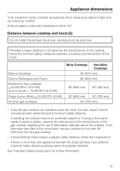
... Non-Miele Cooktops 24" (610 mm) 26" (660 mm) 26" (660 mm) 30" (760 mm) 26" (660 mm) 30" (760 mm) 30" (760 mm) - Appliance dimensions 1) Air extraction mode; muffler). 2) Recirculation mode with Installation kit DUU 151 Distance between a cooktop and the bottom of the cooktop, follow ...than one appliance beneath the hood and they have different minimum safety distances always select the greater distance. If several gas surfaces are installed under the hood, the total output must be considered when determining the minimum safety distance. - If local building codes require a greater...
... Non-Miele Cooktops 24" (610 mm) 26" (660 mm) 26" (660 mm) 30" (760 mm) 26" (660 mm) 30" (760 mm) 30" (760 mm) - Appliance dimensions 1) Air extraction mode; muffler). 2) Recirculation mode with Installation kit DUU 151 Distance between a cooktop and the bottom of the cooktop, follow ...than one appliance beneath the hood and they have different minimum safety distances always select the greater distance. If several gas surfaces are installed under the hood, the total output must be considered when determining the minimum safety distance. - If local building codes require a greater...

Operating and Installation manual
Page 24
Installation Installation accessories 24
Installation Installation accessories 24
Operating and Installation manual
Page 25
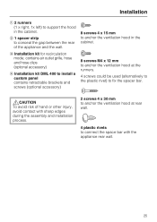
... cabinet. b 1 spacer strip to conceal the gap between the rear of hand or other injury, avoid contact with sharp edges during the assembly and installation process. 2 screws 4 x 30 mm to anchor the ventilation hood at the runners. 4 screws could be used (alternatively to the plastic rivet)... to fix the spacer bar. ,CAUTION To avoid risk of the appliance and the wall. c Installation kit for recirculation mode; Installation a 2 runners (1 x right, 1x left) to support the hood in the cabinet. 8 screws M4 x 12 mm to anchor the ...
... cabinet. b 1 spacer strip to conceal the gap between the rear of hand or other injury, avoid contact with sharp edges during the assembly and installation process. 2 screws 4 x 30 mm to anchor the ventilation hood at the runners. 4 screws could be used (alternatively to the plastic rivet)... to fix the spacer bar. ,CAUTION To avoid risk of the appliance and the wall. c Installation kit for recirculation mode; Installation a 2 runners (1 x right, 1x left) to support the hood in the cabinet. 8 screws M4 x 12 mm to anchor the ...
Operating and Installation manual
Page 27
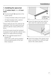
...sits flush with the wall under the cabinet side walls. ^ At the front edge of the spacer strip draw a vertical line on the custom panel: - Installing the space bar T = K cabinet depth minus G hood depth ^ The hood depth G depends on left and right side of the next lower measure. ^... corpus (without front panel - Clip it with a knife at the predetermined breaking point of the inside cabinet. 27 a Hood installed without the door). If the front panel should be installed recessed or flush with the cabinet door, adjust the measure T accordingly. ^ Cut the supplied space bar to measure...
...sits flush with the wall under the cabinet side walls. ^ At the front edge of the spacer strip draw a vertical line on the custom panel: - Installing the space bar T = K cabinet depth minus G hood depth ^ The hood depth G depends on left and right side of the next lower measure. ^... corpus (without front panel - Clip it with a knife at the predetermined breaking point of the inside cabinet. 27 a Hood installed without the door). If the front panel should be installed recessed or flush with the cabinet door, adjust the measure T accordingly. ^ Cut the supplied space bar to measure...

Operating and Installation manual
Page 28
Screw the runners on its back side. Installing the hood in the cabinet ^ Lay the hood on the left and right side in the cabinet. ^ Hold the grease filter and pull it out ... wall measure. ^ Align the runners with the drawn line and be sure that they are flush with the deflector. 28 Do not remove the installation protector between the deflector and casing before the installation is completed. Runners 3. Installation 2. Screw on the angled side which has the imprint of 5/8" (16 mm) and 3/4" (19 mm).
Screw the runners on its back side. Installing the hood in the cabinet ^ Lay the hood on the left and right side in the cabinet. ^ Hold the grease filter and pull it out ... wall measure. ^ Align the runners with the drawn line and be sure that they are flush with the deflector. 28 Do not remove the installation protector between the deflector and casing before the installation is completed. Runners 3. Installation 2. Screw on the angled side which has the imprint of 5/8" (16 mm) and 3/4" (19 mm).
Operating and Installation manual
Page 29
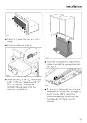
Installation ^ Take the grease filter out and put it aside. ^ Push the deflector back in. ^ Insert the hood into the cabinet from the cabinet. 29 The installation springs loosen and the hood can be removed from below and until the spring clips click into place. ^ When installing a 29 13/16" (80 cm) or a 35 1/4" (90 cm) hood into a 23 5/8" (60 cm) cabinet, unscrew the deflector spring clips while the deflector is pulled out. ^ To dismount the appliance: unscrew the screws to the left and the right of the inner side of the hood.
Installation ^ Take the grease filter out and put it aside. ^ Push the deflector back in. ^ Insert the hood into the cabinet from the cabinet. 29 The installation springs loosen and the hood can be removed from below and until the spring clips click into place. ^ When installing a 29 13/16" (80 cm) or a 35 1/4" (90 cm) hood into a 23 5/8" (60 cm) cabinet, unscrew the deflector spring clips while the deflector is pulled out. ^ To dismount the appliance: unscrew the screws to the left and the right of the inner side of the hood.
Operating and Installation manual
Page 30
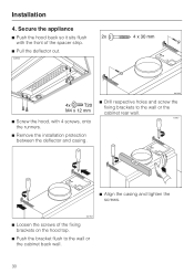
Installation 4. Secure the appliance ^ Push the hood back so it sits flush with the front of the spacer strip. ^ Pull the deflector out. ^ Screw the hood, with 4 screws, onto the runners. ^ Remove the installation protection between the deflector and casing. ^ Drill respective holes and screw the fixing brackets to the wall or the cabinet rear wall. ^ Align the casing and tighten the screws. ^ Loosen the screws of the fixing brackets on the hood top. ^ Push the bracket flush to the wall or the cabinet back wall. 30
Installation 4. Secure the appliance ^ Push the hood back so it sits flush with the front of the spacer strip. ^ Pull the deflector out. ^ Screw the hood, with 4 screws, onto the runners. ^ Remove the installation protection between the deflector and casing. ^ Drill respective holes and screw the fixing brackets to the wall or the cabinet rear wall. ^ Align the casing and tighten the screws. ^ Loosen the screws of the fixing brackets on the hood top. ^ Push the bracket flush to the wall or the cabinet back wall. 30

Operating and Installation manual
Page 31
...30 mm). This applies for front panels with the front of the panel, for instance. ^ Connect the space bar from Miele. Install the front panel if necessary The installation kit DML 400 is flush with a depth of the front panel must be reduced by milling out the back of the adjacent... cabinetry. 31 Adjust the deflector until it is necessary. The installation kit has an installation manual supplied. ^ The deflector can be adjusted up to 1 3/8" (35 mm) towards the front with 4 plastic rivets at the ...
...30 mm). This applies for front panels with the front of the panel, for instance. ^ Connect the space bar from Miele. Install the front panel if necessary The installation kit DML 400 is flush with a depth of the front panel must be reduced by milling out the back of the adjacent... cabinetry. 31 Adjust the deflector until it is necessary. The installation kit has an installation manual supplied. ^ The deflector can be adjusted up to 1 3/8" (35 mm) towards the front with 4 plastic rivets at the ...
Operating and Installation manual
Page 32
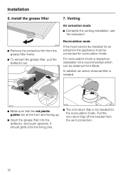
Install the grease filter ^ Remove the protective film from Miele. It should glide onto the fixing pins. ^ The non-return flap is not needed . ^ Make sure that the red plastic guides are at the front ...and facing up. ^ Insert the grease filter into the deflector, and push upwards. Venting Air extraction mode ^ Complete the venting installation, see "Air extraction". Installation 6. For...
Install the grease filter ^ Remove the protective film from Miele. It should glide onto the fixing pins. ^ The non-return flap is not needed . ^ Make sure that the red plastic guides are at the front ...and facing up. ^ Insert the grease filter into the deflector, and push upwards. Venting Air extraction mode ^ Complete the venting installation, see "Air extraction". Installation 6. For...
Operating and Installation manual
Page 33
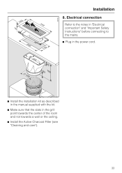
Electrical connection Refer to the notes in "Electrical connection" and "Important Safety Instructions" before connecting to the mains. ^ Plug in the power cord. ^ Install the installation kit as described in the manual supplied with the kit. ^ Make sure that the slats in the grill point towards the center of the room and not towards a wall or the ceiling. ^ Install the Active Charcoal Filter (see "Cleaning and care"). 33 Installation 8.
Electrical connection Refer to the notes in "Electrical connection" and "Important Safety Instructions" before connecting to the mains. ^ Plug in the power cord. ^ Install the installation kit as described in the manual supplied with the kit. ^ Make sure that the slats in the grill point towards the center of the room and not towards a wall or the ceiling. ^ Install the Active Charcoal Filter (see "Cleaning and care"). 33 Installation 8.
