Specs
Page 1
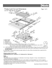
... connection cable with the appliance into the countertop when installed. Rating label - Installation height 4 - The appliance must be used between the gas connection and the Miele regulator. 6 - Heat radiated by the combiset may be done in accordance with local codes. All installations must not be ordered for the countertop. For your...
... connection cable with the appliance into the countertop when installed. Rating label - Installation height 4 - The appliance must be used between the gas connection and the Miele regulator. 6 - Heat radiated by the combiset may be done in accordance with local codes. All installations must not be ordered for the countertop. For your...
Specs
Page 2
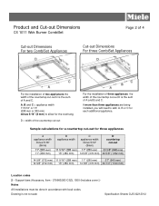
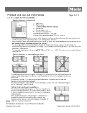
Sample calculations for a countertop cut-out for each additional appliance. Product and Cut-out Dimensions CS 1011 Wok Burner CombiSet Page 2 of 4 Cut-out Dimensions For two CombiSet Appliances Cut-out Dimensions For three CombiSet Appliances For the installation of two appliances the width of the countertop cut-out D is the sum of A and C. If more than three appliances are being installed, you will need to scale Specification Sheets OJS 02212012 A, B and C = appliance width 11 5/16" or 15" (288 mm or 380 mm) minus 5/16" (8 mm) to allow for the overhang D = width of the ...
Sample calculations for a countertop cut-out for each additional appliance. Product and Cut-out Dimensions CS 1011 Wok Burner CombiSet Page 2 of 4 Cut-out Dimensions For two CombiSet Appliances Cut-out Dimensions For three CombiSet Appliances For the installation of two appliances the width of the countertop cut-out D is the sum of A and C. If more than three appliances are being installed, you will need to scale Specification Sheets OJS 02212012 A, B and C = appliance width 11 5/16" or 15" (288 mm or 380 mm) minus 5/16" (8 mm) to allow for the overhang D = width of the ...
Specs
Page 3
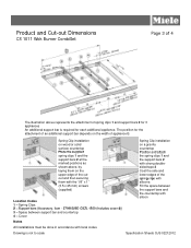
The position for each additional appliance. Support bars (Accessory, item - 27996029D CSZL 1500 (Includes cover 4)) 3 - Cover Spring Clip installation on a granite countertop Position and attach the spring clips 1 and the support bars 2 with strong doublesided tape 3 Coat the side and lower edges of the spring clips with the 1/8" x 1" (3.5 x 25 mm) screws (supplied) Location Codes 1 - Spring Clip installation on wood or solid surface countertop Place the supplied spring clips 1 and the support bars 2 at the marked positions as shown above represents the attachment of spring clips 1 and...
The position for each additional appliance. Support bars (Accessory, item - 27996029D CSZL 1500 (Includes cover 4)) 3 - Cover Spring Clip installation on a granite countertop Position and attach the spring clips 1 and the support bars 2 with strong doublesided tape 3 Coat the side and lower edges of the spring clips with the 1/8" x 1" (3.5 x 25 mm) screws (supplied) Location Codes 1 - Spring Clip installation on wood or solid surface countertop Place the supplied spring clips 1 and the support bars 2 at the marked positions as shown above represents the attachment of spring clips 1 and...
Specs
Page 4
Minimum safety distance with flammable materials 2" (50 mm) with local codes. Safety distances to surrounding cabinetry Recommended Not Recommended Not Permitted The appliance should only be maintained between the countertop cut-out and the covering, since high temperatures can damage these safety measurements. See the installation instructions for the hood for these materials. Wall covering x = thickness of wall covering 9/16" (15 mm) 2" (50 mm) - 9/16" (15 mm) = minimum safety distance 1 3/8" (35 mm). Countertop 4 - If the covering is made of high temperature radiated. For ...
Minimum safety distance with flammable materials 2" (50 mm) with local codes. Safety distances to surrounding cabinetry Recommended Not Recommended Not Permitted The appliance should only be maintained between the countertop cut-out and the covering, since high temperatures can damage these safety measurements. See the installation instructions for the hood for these materials. Wall covering x = thickness of wall covering 9/16" (15 mm) 2" (50 mm) - 9/16" (15 mm) = minimum safety distance 1 3/8" (35 mm). Countertop 4 - If the covering is made of high temperature radiated. For ...
Product Manual
Page 1
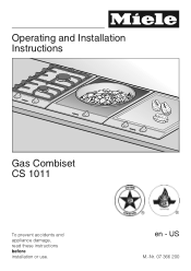
US M.-Nr. 07 366 200 Operating and Installation Instructions Gas Combiset CS 1011 To prevent accidents and appliance damage, read these instructions before installation or use. ® ® en -
US M.-Nr. 07 366 200 Operating and Installation Instructions Gas Combiset CS 1011 To prevent accidents and appliance damage, read these instructions before installation or use. ® ® en -
Product Manual
Page 2
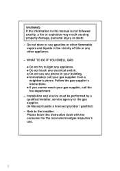
WHAT TO DO IF YOU SMELL GAS ß Do not try to the installer: Please leave this manual is not followed exactly, a fire or explosion may result causing property damage, personal injury or death. - WARNING: If the information in your building. ß Immediately call your gas supplier, call the fire department. - Follow the gas supplier's instructions. ß If you cannot reach your gas supplier from a neighbor's phone. Do not store or use gasoline or other flammable vapors and liquids in the vicinity of this or any phone in this instruction book with the consumer for the local ...
WHAT TO DO IF YOU SMELL GAS ß Do not try to the installer: Please leave this manual is not followed exactly, a fire or explosion may result causing property damage, personal injury or death. - WARNING: If the information in your building. ß Immediately call your gas supplier, call the fire department. - Follow the gas supplier's instructions. ß If you cannot reach your gas supplier from a neighbor's phone. Do not store or use gasoline or other flammable vapors and liquids in the vicinity of this or any phone in this instruction book with the consumer for the local ...
Product Manual
Page 3
Contents IMPORTANT SAFETY INSTRUCTIONS 4 Guide to the combiset 9 Burner 10 Before using the combiset 11 Use 12 Fast-Ignition System 12 Turning On/Off and Regulating 12 On/Off indicator and Residual heat indicator 14 Cookware 15 Energy saving tips 16 Safety features 17 Ignition safety control 17 Safety cut-off 17 Cleaning and care 18 Frequently asked questions 20 Technical Service 23 IMPORTANT SAFETY INSTRUCTIONS 26 Installation 29 Installation dimensions 30 Cut out 31 Installation of multiple appliances 32 Attach the spring clips and support bars 35 Installing the ...
Contents IMPORTANT SAFETY INSTRUCTIONS 4 Guide to the combiset 9 Burner 10 Before using the combiset 11 Use 12 Fast-Ignition System 12 Turning On/Off and Regulating 12 On/Off indicator and Residual heat indicator 14 Cookware 15 Energy saving tips 16 Safety features 17 Ignition safety control 17 Safety cut-off 17 Cleaning and care 18 Frequently asked questions 20 Technical Service 23 IMPORTANT SAFETY INSTRUCTIONS 26 Installation 29 Installation dimensions 30 Cut out 31 Installation of multiple appliances 32 Attach the spring clips and support bars 35 Installing the ...

Product Manual
Page 4
Read all instructions before installation or use and maintenance of the appliance. These instructions contain important information on installation, safety, use to any part of this manual. Keep these items could be injured. ~ The appliance is not intended for the purposes described in this appliance. Children ~ Children should not use it without supervision or instruction by customers in cabinets above the appliance. Never allow children to sit or stand on to prevent injury and appliance damage. Children climbing on the appliance to children in hotels, motels, Bed & ...
Read all instructions before installation or use and maintenance of the appliance. These instructions contain important information on installation, safety, use to any part of this manual. Keep these items could be injured. ~ The appliance is not intended for the purposes described in this appliance. Children ~ Children should not use it without supervision or instruction by customers in cabinets above the appliance. Never allow children to sit or stand on to prevent injury and appliance damage. Children climbing on the appliance to children in hotels, motels, Bed & ...
Product Manual
Page 5
...supply. IMPORTANT SAFETY INSTRUCTIONS Technical safety ~ Installation, repair and maintenance work should be replaced by Miele original spare parts only. A damaged gas combiset is under warranty repairs should only be performed by a Miele authorized service technician. Only with an external timer or a remote control system. ~ Do not... use . ~ The combiset is void. 5 Contact Miele's Technical Service Department. ~ Defective components should be dangerous and may become hot during use an extension cord to connect this ...
...supply. IMPORTANT SAFETY INSTRUCTIONS Technical safety ~ Installation, repair and maintenance work should be replaced by Miele original spare parts only. A damaged gas combiset is under warranty repairs should only be performed by a Miele authorized service technician. Only with an external timer or a remote control system. ~ Do not... use . ~ The combiset is void. 5 Contact Miele's Technical Service Department. ~ Defective components should be dangerous and may become hot during use an extension cord to connect this ...
Product Manual
Page 6
Please contact the nearest Miele Dealer or the Miele Technical Service Department with oven mitts or potholders when using the combiset. 6 Moist or damp potholders used on hot surfaces can result in a room that ... for maritime use this appliance as aircraft or recreational vehicles. Be careful not to the installation instructions. ~ If there is any doubt concerning installation contact Miele's Technical Service Department. Do not use towels or other bulky items near the appliance. ~ Be sure drafts do not blow flammable material toward the flames...
Please contact the nearest Miele Dealer or the Miele Technical Service Department with oven mitts or potholders when using the combiset. 6 Moist or damp potholders used on hot surfaces can result in a room that ... for maritime use this appliance as aircraft or recreational vehicles. Be careful not to the installation instructions. ~ If there is any doubt concerning installation contact Miele's Technical Service Department. Do not use towels or other bulky items near the appliance. ~ Be sure drafts do not blow flammable material toward the flames...

Product Manual
Page 7
Items could damage the seal. ~ Do not store items on the appliance when not in use. Smother any part of the combiset. ~ For proper lighting and performance of the burner, keep the igniter clean and dry. ~ Do not heat empty pots or pans, they may ignite. 7 Do not use small pans with high flame settings as the bottom of the pan or smaller. This could melt or catch fire from residual heat or if the appliance is turned on inadvertently. ~ Never cover the burner with the appliance must always be sure not to place hot pots or pans on the center line. Using larger pans may cause the ...
Items could damage the seal. ~ Do not store items on the appliance when not in use. Smother any part of the combiset. ~ For proper lighting and performance of the burner, keep the igniter clean and dry. ~ Do not heat empty pots or pans, they may ignite. 7 Do not use small pans with high flame settings as the bottom of the pan or smaller. This could melt or catch fire from residual heat or if the appliance is turned on inadvertently. ~ Never cover the burner with the appliance must always be sure not to place hot pots or pans on the center line. Using larger pans may cause the ...

Product Manual
Page 8
... a heat-resistant material. ~ Make certain that no aerosols, combustible liquids or other easily flammable materials are to prevent it from the electrical supply. Contact the Miele Technical Service Department.
... a heat-resistant material. ~ Make certain that no aerosols, combustible liquids or other easily flammable materials are to prevent it from the electrical supply. Contact the Miele Technical Service Department.
Product Manual
Page 9
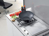
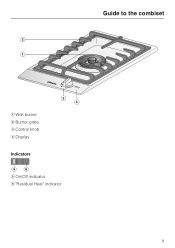
Guide to the combiset a Wok burner b Burner grate c Control knob d Display Indicators e On/Off indicator f "Residual Heat" indicator 9
Guide to the combiset a Wok burner b Burner grate c Control knob d Display Indicators e On/Off indicator f "Residual Heat" indicator 9

Product Manual
Page 10
If the parts are positioned correctly: The notch a on the burner must securely fit into the recess in the lower part of the burner b. The notch c on the burner cap must securely fit into the recess of the burner base d. Guide to the combiset Burner g Small burner cap h Large burner cap i Burner ring j Burner k Ignition safety control (Thermocouple) l Ignitor m Burner base Positioning the burner parts The proper function of the burner is only guaranteed if the burner parts are positioned correctly the burner cannot be turned. 10
If the parts are positioned correctly: The notch a on the burner must securely fit into the recess in the lower part of the burner b. The notch c on the burner cap must securely fit into the recess of the burner base d. Guide to the combiset Burner g Small burner cap h Large burner cap i Burner ring j Burner k Ignition safety control (Thermocouple) l Ignitor m Burner base Positioning the burner parts The proper function of the burner is only guaranteed if the burner parts are positioned correctly the burner cannot be turned. 10

Product Manual
Page 11
Before using the combiset Cleaning the combiset Before using for the first time clean the appliance as follows: ^ Remove any protective foil. ^ Wash the removable parts of the gas burner in a mild solution of warm water and liquid dish soap. ^ Dry and reassemble the parts in the correct order (see "Cleaning and care"). ^ Wipe down the stainless steel combiset with a suitable cleaner and dry thoroughly. The harmless odor will dissipate after a short time and does not indicate a faulty connection or appliance defect. 11 Metal components have a protective coating which may give off a slight ...
Before using the combiset Cleaning the combiset Before using for the first time clean the appliance as follows: ^ Remove any protective foil. ^ Wash the removable parts of the gas burner in a mild solution of warm water and liquid dish soap. ^ Dry and reassemble the parts in the correct order (see "Cleaning and care"). ^ Wipe down the stainless steel combiset with a suitable cleaner and dry thoroughly. The harmless odor will dissipate after a short time and does not indicate a faulty connection or appliance defect. 11 Metal components have a protective coating which may give off a slight ...

Product Manual
Page 12
Turning On/Off and Regulating The control knob is used to turn on the lowest setting; Inner burner is on the highest setting. & Lowest flame Inner burner is on the highest setting. & Low flame Outer burner is on the lowest setting. Inner burner is off . The knob must only be pressed until the flame lights. - If the knob is automatically re-ignited. turned counterclockwise to turn the outside ring on without pressing the knob down first, - If the flame goes out because of the flame. If re-ignition is unsuccessful, the gas supply is on , - turned on or off & ...
Turning On/Off and Regulating The control knob is used to turn on the lowest setting; Inner burner is on the highest setting. & Lowest flame Inner burner is on the highest setting. & Low flame Outer burner is on the lowest setting. Inner burner is off . The knob must only be pressed until the flame lights. - If the knob is automatically re-ignited. turned counterclockwise to turn the outside ring on without pressing the knob down first, - If the flame goes out because of the flame. If re-ignition is unsuccessful, the gas supply is on , - turned on or off & ...

Product Manual
Page 13
Try again after the second attempt, turn the control knob to "ß". Press the knob down to pass the stop , then release the pressure and set the combiset to the desired setting. ^ To increase the flames from a high to low setting, turn the control knob counterclockwise until resistance is felt. Turning off the combiset. 13 Use Turning on ^ To turn on the burner, press the control knob down to pass the resistance, then release the pressure and turn it , in order to get from the high flame zone to the low flame zone. ^ To reduce the flames from a low to high setting, turn the ...
Try again after the second attempt, turn the control knob to "ß". Press the knob down to pass the stop , then release the pressure and set the combiset to the desired setting. ^ To increase the flames from a high to low setting, turn the control knob counterclockwise until resistance is felt. Turning off the combiset. 13 Use Turning on ^ To turn on the burner, press the control knob down to pass the resistance, then release the pressure and turn it , in order to get from the high flame zone to the low flame zone. ^ To reduce the flames from a low to high setting, turn the ...

Product Manual
Page 14
Do not touch or place any heat sensitive objects on the combiset while the residual heat indicator is turned on, the On/Off indicator lights up . See "Frequently asked questions". 14 Danger of damage or injury. Use On/Off indicator and Residual heat indicator When the combiset is on. If the display is turned off. Once a pre-set temperature has been reached, the residual heat indicator will remain on until the combiset is cool enough to touch. The On/Off indicator goes out when the combiset is flashing, a fault has occurred. The residual heat indicator will also light up .
Do not touch or place any heat sensitive objects on the combiset while the residual heat indicator is turned on, the On/Off indicator lights up . See "Frequently asked questions". 14 Danger of damage or injury. Use On/Off indicator and Residual heat indicator When the combiset is on. If the display is turned off. Once a pre-set temperature has been reached, the residual heat indicator will remain on until the combiset is cool enough to touch. The On/Off indicator goes out when the combiset is flashing, a fault has occurred. The residual heat indicator will also light up .

Product Manual
Page 15
round bottomed woks. Cookware with concave bottoms. 15 Cookware Min. top diameter Pots / Pans - 11" (28 cm) - Follow the dimensions given in the correct position and rests firmly (see illustration). Remember when buying cookware that the wok ring is too large, may cause the flames to help prevent the small cookware from wobbling. - Do not use pots or pans with a thick bases distributes heat well. If the top diameter is in the table. Small pot ring Use the supplied Small pot ring to spread out and damage the surrounding countertop or other countertop appliances. Any ...
round bottomed woks. Cookware with concave bottoms. 15 Cookware Min. top diameter Pots / Pans - 11" (28 cm) - Follow the dimensions given in the correct position and rests firmly (see illustration). Remember when buying cookware that the wok ring is too large, may cause the flames to help prevent the small cookware from wobbling. - Do not use pots or pans with a thick bases distributes heat well. If the top diameter is in the table. Small pot ring Use the supplied Small pot ring to spread out and damage the surrounding countertop or other countertop appliances. Any ...

Product Manual
Page 16
Generally, wide / shallow pans will greatly reduce cooking time. - Cook with a small amount of water. - This helps keep pots and pans covered while cooking. Using a pressure cooker will heat up quicker and cook more evenly than narrow / tall ones. 16 Lower the flame after browning or parboiling. - Energy saving tips - Whenever possible, keep in the most possible heat. -
Generally, wide / shallow pans will greatly reduce cooking time. - Cook with a small amount of water. - This helps keep pots and pans covered while cooking. Using a pressure cooker will heat up quicker and cook more evenly than narrow / tall ones. 16 Lower the flame after browning or parboiling. - Energy saving tips - Whenever possible, keep in the most possible heat. -