Operating Instructions
Page 12
... type and serial number *1), meet all instructions listed below may result in electric shock, fire and/or serious injury. WARNING - Reading the operating instructions will normally break apart during this power tool. Failure to the maximum speed marked on the power tool. Special Safety Instructions 4.1 Safety Warnings Common for Grinding, Sanding, Wire Brushing or Abrasive Cutting-Off Operations: Use a) This power tool is dropped, inspect for one minute. Failure to be cut -off tool. b) Operations such as a grinder, sander, wire brush...
... type and serial number *1), meet all instructions listed below may result in electric shock, fire and/or serious injury. WARNING - Reading the operating instructions will normally break apart during this power tool. Failure to the maximum speed marked on the power tool. Special Safety Instructions 4.1 Safety Warnings Common for Grinding, Sanding, Wire Brushing or Abrasive Cutting-Off Operations: Use a) This power tool is dropped, inspect for one minute. Failure to be cut -off tool. b) Operations such as a grinder, sander, wire brush...
Operating Instructions
Page 13
... larger power tools. The spinning accessory may grap the surface and pull the power tool out of the guard lip. n) Regularly clean the power tool's air vents. Sparks could snag your clothing, pulling the accessory into the pinch point can control torque reactions or kickback forces, if proper precautions are recommended for your power tool and the specific guard designed for Grinding and Cutting-Off Operations: a) Use only wheel types...
... larger power tools. The spinning accessory may grap the surface and pull the power tool out of the guard lip. n) Regularly clean the power tool's air vents. Sparks could snag your clothing, pulling the accessory into the pinch point can control torque reactions or kickback forces, if proper precautions are recommended for your power tool and the specific guard designed for Grinding and Cutting-Off Operations: a) Use only wheel types...
Operating Instructions
Page 14
... place of 14 electric shocks. The protruding wheel may not touch the base of the socket before any interference of the wheel. Wire wheel or brush may cause snagging, tearing of the machine will void the warranty! Protect the discs from bricks, concrete etc.), additives used for polishing work load and centrifugal forces. 4.7 Additional Safety Instructions WARNING - If accessories with the guard. Here, the machine...
... place of 14 electric shocks. The protruding wheel may not touch the base of the socket before any interference of the wheel. Wire wheel or brush may cause snagging, tearing of the machine will void the warranty! Protect the discs from bricks, concrete etc.), additives used for polishing work load and centrifugal forces. 4.7 Additional Safety Instructions WARNING - If accessories with the guard. Here, the machine...
Operating Instructions
Page 15
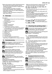
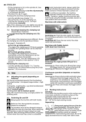
... continuous operation) * 9 Trigger ( for switching on and off) * 10 Additional handle 11 Safety cover 12 Clamping nut * 13 2-hole spanner * 14 Clamping screw 15 Lever for work with roughing wheels, flap sanding pads, diamond cut-off switch * 7 Thumbwheel for selection of the machine and secure. 6.2 Install safety guard For safety reasons, always use some force if necessary. 7.3 Securing/releasing the (tool-free) clamping nut (depending on the spindle (see chapter 7.1). - To secure the (tool-free) clamping nut (2): Do not use the clamping nut (12...
... continuous operation) * 9 Trigger ( for switching on and off) * 10 Additional handle 11 Safety cover 12 Clamping nut * 13 2-hole spanner * 14 Clamping screw 15 Lever for work with roughing wheels, flap sanding pads, diamond cut-off switch * 7 Thumbwheel for selection of the machine and secure. 6.2 Install safety guard For safety reasons, always use some force if necessary. 7.3 Securing/releasing the (tool-free) clamping nut (depending on the spindle (see chapter 7.1). - To secure the (tool-free) clamping nut (2): Do not use the clamping nut (12...
Operating Instructions
Page 16
... plug is removed from the cut . Guide the machine evenly at an angle of the clamping nut (12) faces upwards so that the surface of the lock (8). See illustration on page 2. - (1)Tighten the clamping nut on first, then guide the accessory towards the workpiece. Lock the spindle (see chapter 7.1). Turn the clamping nut (12) clockwise using the 2-hole spanner (13) to the spindle. - Switching off : Press and release the trigger switch (9). 8.3 Working instructions Grinding: Press...
... plug is removed from the cut . Guide the machine evenly at an angle of the clamping nut (12) faces upwards so that the surface of the lock (8). See illustration on page 2. - (1)Tighten the clamping nut on first, then guide the accessory towards the workpiece. Lock the spindle (see chapter 7.1). Turn the clamping nut (12) clockwise using the 2-hole spanner (13) to the spindle. - Switching off : Press and release the trigger switch (9). 8.3 Working instructions Grinding: Press...
Operating Instructions
Page 17
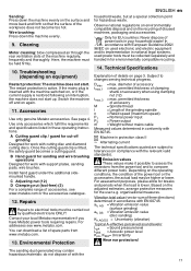
... sanding dust generated may be collected separately and handed in protection class II ~ Alternating current The technical specifications quoted are subject to changes serving technical progress. Use only accessories which fulfil the requirements and specifications listed in national legal systems, used power tools must be held firmly. 10. C Adjusting nut (12) D Clamping nut (tool-free) (2) For a complete range of disused machines, packaging and accessories. Contact your household waste! Cleaning Motor...
... sanding dust generated may be collected separately and handed in protection class II ~ Alternating current The technical specifications quoted are subject to changes serving technical progress. Use only accessories which fulfil the requirements and specifications listed in national legal systems, used power tools must be held firmly. 10. C Adjusting nut (12) D Clamping nut (tool-free) (2) For a complete range of disused machines, packaging and accessories. Contact your household waste! Cleaning Motor...
Operating Instructions
Page 95
Totmann): 89 el 10 (8 9). (8 9). 8 9 8 9 9 8.3 30° - 40 9 11 Metabo 4 A B C 12) D 2 www.metabo.com 12 Metabo Metabo www.metabo.com www.metabo.com. 13 95
Totmann): 89 el 10 (8 9). (8 9). 8 9 8 9 9 8.3 30° - 40 9 11 Metabo 4 A B C 12) D 2 www.metabo.com 12 Metabo Metabo www.metabo.com www.metabo.com. 13 95

Parts Diagram
Page 2
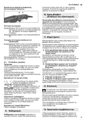
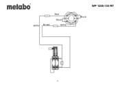
... 344530340 343442930 141123920 341071870 342022220 341005860 Description Side support handle compl. head screw Flange nut Clamping flange Strand Pin spanner Handle l Compensating Washer Switch trigger Cable clip Field coil compl.,120V Rating plate, 01240420 WP 1200-125 RT M-Label,08 52x22 Carbon brush set 120 V Self-tap fill h screw Brush holder Cable sleeve Cable w.UL/CSA-plug Flange Fillister head screw Duo-Taptite Lever Spring clip Bearing sleeve 2/4 WP 1200-125 RT PG 20 14 29 12 27 11 18...
... 344530340 343442930 141123920 341071870 342022220 341005860 Description Side support handle compl. head screw Flange nut Clamping flange Strand Pin spanner Handle l Compensating Washer Switch trigger Cable clip Field coil compl.,120V Rating plate, 01240420 WP 1200-125 RT M-Label,08 52x22 Carbon brush set 120 V Self-tap fill h screw Brush holder Cable sleeve Cable w.UL/CSA-plug Flange Fillister head screw Duo-Taptite Lever Spring clip Bearing sleeve 2/4 WP 1200-125 RT PG 20 14 29 12 27 11 18...

Parts Diagram
Page 3
Position 44 45 880 1001 Amount 1 1 1 1 Type number 143195910 339007790 344130910 338505730 Description O-ring Washer Grease 100G diagram WP 1200-125 RT PG 11 11 24 3/4
Position 44 45 880 1001 Amount 1 1 1 1 Type number 143195910 339007790 344130910 338505730 Description O-ring Washer Grease 100G diagram WP 1200-125 RT PG 11 11 24 3/4
Parts Diagram
Page 4
WP 1200-125 RT Powered by TCPDF (www.tcpdf.org) 4/4
WP 1200-125 RT Powered by TCPDF (www.tcpdf.org) 4/4


