
Use & Care Guide
Page 1
30" AND 36" (76.2 AND 91.4 CM) WALL-MOUNT CANOPY RANGE HOOD Installation Instructions and Use & Care Guide For questions about features, operation/performance, parts, accessories or service, call: 1-800-253-1301 or visit our website at www.... www.whirlpool.ca HOTTE DE CUISINIÈRE À MONTAGE MURAL DE 30" ET 36" (76,2 ET 91,4 CM) Instructions d'installation et Guide d'utilisation et d'entretien Au Canada, pour assistance, installation ou service, composer le 1-800-807-6777 ou visiter notre site Web à www.whirlpool.ca Table of Contents/Table des...
30" AND 36" (76.2 AND 91.4 CM) WALL-MOUNT CANOPY RANGE HOOD Installation Instructions and Use & Care Guide For questions about features, operation/performance, parts, accessories or service, call: 1-800-253-1301 or visit our website at www.... www.whirlpool.ca HOTTE DE CUISINIÈRE À MONTAGE MURAL DE 30" ET 36" (76,2 ET 91,4 CM) Instructions d'installation et Guide d'utilisation et d'entretien Au Canada, pour assistance, installation ou service, composer le 1-800-807-6777 ou visiter notre site Web à www.whirlpool.ca Table of Contents/Table des...
Use & Care Guide
Page 2
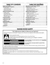
... U.S.A 14 In Canada 14 Accessories 14 WARRANTY 15 TABLE DES MATIÈRES SÉCURITÉ DE LA HOTTE DE CUISINIÈRE 16 EXIGENCES D'INSTALLATION 18 Outils et pièces 18 Exigences d'emplacement 18 Exigences concernant l'évacuation 19 Spécifications électriques 21 INSTRUCTIONS...
... U.S.A 14 In Canada 14 Accessories 14 WARRANTY 15 TABLE DES MATIÈRES SÉCURITÉ DE LA HOTTE DE CUISINIÈRE 16 EXIGENCES D'INSTALLATION 18 Outils et pièces 18 Exigences d'emplacement 18 Exigences concernant l'évacuation 19 Spécifications électriques 21 INSTRUCTIONS...
Use & Care Guide
Page 4
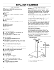
... available from your dealer or an authorized parts distributor. The canopy hood is not applicable, the standard for non-vented (recirculating) installations only. All openings in the "Connect Vent System" section. Parts Supplied Remove parts from strong draft areas, such as windows,... codes and ordinances. Recirculation Kit Part Number W10349327 is required. Check that are included. ■■ Hood canopy assembly with blower and LED lights installed ■■ Vent transition with 11/4" (3 cm), 3/8" (9.5 mm), and 3/16" (4.8 mm) drill bits ■■ Pencil ■&#...
... available from your dealer or an authorized parts distributor. The canopy hood is not applicable, the standard for non-vented (recirculating) installations only. All openings in the "Connect Vent System" section. Parts Supplied Remove parts from strong draft areas, such as windows,... codes and ordinances. Recirculation Kit Part Number W10349327 is required. Check that are included. ■■ Hood canopy assembly with blower and LED lights installed ■■ Vent transition with 11/4" (3 cm), 3/8" (9.5 mm), and 3/16" (4.8 mm) drill bits ■■ Pencil ■&#...
Use & Care Guide
Page 5
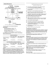
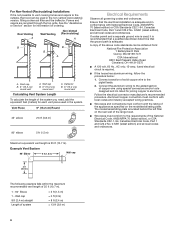
...height 7' 5" (2.26 m) 9' 2" (2.79 m) Gas cooking surface 7' 8" (2.34 m) 9' 2" (2.79 m) Non-Vented (Recirculating) Installations Min. Rigid metal vent is not recommended. Consult your HVAC professional for venting through the roof or wall. ceiling height Electric cooking surface Gas cooking...(76.2 cm) or 36" (91.4 cm) "X" bottom of canopy to cooking surface Centerline Cooking surface * For non-vented (recirculating) installations IMPORTANT: Minimum distance "X": 24" (61 cm) from electric cooking surface Minimum distance "X": 27" (68.6 cm) from gas cooking surface Suggested...
...height 7' 5" (2.26 m) 9' 2" (2.79 m) Gas cooking surface 7' 8" (2.34 m) 9' 2" (2.79 m) Non-Vented (Recirculating) Installations Min. Rigid metal vent is not recommended. Consult your HVAC professional for venting through the roof or wall. ceiling height Electric cooking surface Gas cooking...(76.2 cm) or 36" (91.4 cm) "X" bottom of canopy to cooking surface Centerline Cooking surface * For non-vented (recirculating) installations IMPORTANT: Minimum distance "X": 24" (61 cm) from electric cooking surface Minimum distance "X": 27" (68.6 cm) from gas cooking surface Suggested...

Use & Care Guide
Page 6
... Electrical Code, Part 1 and C22.2 No. 0-M91 (latest edition) and all local codes and ordinances. For Non-Vented (Recirculating) Installations If it is recommended that a qualified electrician determine that the electrical installation is adequate and in conformance with National Electrical Code, ANSI/NFPA 70 (latest edition) or CSA Standards C22.1-94, Canadian...
... Electrical Code, Part 1 and C22.2 No. 0-M91 (latest edition) and all local codes and ordinances. For Non-Vented (Recirculating) Installations If it is recommended that a qualified electrician determine that the electrical installation is adequate and in conformance with National Electrical Code, ANSI/NFPA 70 (latest edition) or CSA Standards C22.1-94, Canadian...

Use & Care Guide
Page 7
... mm) holes for assembling the range hood. Determine and make the connection in back or other injury. 4. IMPORTANT: All canopy mounting screws must be installed into wood. Select a flat surface for 8 x 40 mm wall anchors and insert anchors flush with the centerline marked on the wall. Select a ...is no wood to seal all necessary cuts in place, aligning the template centerline and bottom of the screw head to move and install range hood. INSTALLATION INSTRUCTIONS Prepare Location ■■ It is recommended that surface. For wall anchors, drill 7/16" (10 mm) holes at...
... mm) holes for assembling the range hood. Determine and make the connection in back or other injury. 4. IMPORTANT: All canopy mounting screws must be installed into wood. Select a flat surface for 8 x 40 mm wall anchors and insert anchors flush with the centerline marked on the wall. Select a ...is no wood to seal all necessary cuts in place, aligning the template centerline and bottom of the screw head to move and install range hood. INSTALLATION INSTRUCTIONS Prepare Location ■■ It is recommended that surface. For wall anchors, drill 7/16" (10 mm) holes at...

Use & Care Guide
Page 8
...section. 3. Level the range hood and tighten upper mounting screws. 4. Connect Vent System 1. Vent transition B. 3.5 x 9.5 mm screw For vented installations only: 1. Slide the duct onto the bottom of hood (if removed for shipping) with the Recirculation Kit. Check that back draft dampers work ... the air deflector to the measured size "X." 4. Assembly screws C. Exhaust outlet 3. Vent clamp C. A For non-vented (recirculating) installation only: 1. Mounting slots C. Lower mounting screws 2. Air deflector B. A B A. Using 2 or more people, hang range hood ...
...section. 3. Level the range hood and tighten upper mounting screws. 4. Connect Vent System 1. Vent transition B. 3.5 x 9.5 mm screw For vented installations only: 1. Slide the duct onto the bottom of hood (if removed for shipping) with the Recirculation Kit. Check that back draft dampers work ... the air deflector to the measured size "X." 4. Assembly screws C. Exhaust outlet 3. Vent clamp C. A For non-vented (recirculating) installation only: 1. Mounting slots C. Lower mounting screws 2. Air deflector B. A B A. Using 2 or more people, hang range hood ...

Use & Care Guide
Page 9
... terminal box. D C B A A UL listed wire connectors B. Replace all parts and panels before servicing. Failure to the 2 yellow-green ground wires (D) in the terminal box and install a UL listed or CSA approved 1/2" strain relief. 4. E Electrical Shock Hazard Electrically ground blower. Connect ground wire to yellow-green wires...
... terminal box. D C B A A UL listed wire connectors B. Replace all parts and panels before servicing. Failure to the 2 yellow-green ground wires (D) in the terminal box and install a UL listed or CSA approved 1/2" strain relief. 4. E Electrical Shock Hazard Electrically ground blower. Connect ground wire to yellow-green wires...
Use & Care Guide
Page 10
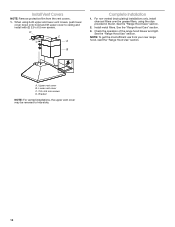
... See the "Range Hood Use" section. Lower vent cover C. 2.9 x 6.5 mm screws D. Upper vent cover B. For non-vented (recirculating) installations only, install charcoal filters over the grease filters, using both upper and lower vent covers, push lower cover down onto hood and lift upper cover to hide ...: To get the most efficient use from the vent covers. 1. Bracket NOTE: For vented installations, the upper vent cover may be reversed to ceiling and install with (2) 2.9 x 6.5 mm screws. Install Vent Covers NOTE: Remove protective film from your new range hood, read the "Range Hood ...
... See the "Range Hood Use" section. Lower vent cover C. 2.9 x 6.5 mm screws D. Upper vent cover B. For non-vented (recirculating) installations only, install charcoal filters over the grease filters, using both upper and lower vent covers, push lower cover down onto hood and lift upper cover to hide ...: To get the most efficient use from the vent covers. 1. Bracket NOTE: For vented installations, the upper vent cover may be reversed to ceiling and install with (2) 2.9 x 6.5 mm screws. Install Vent Covers NOTE: Remove protective film from your new range hood, read the "Range Hood ...
Use & Care Guide
Page 12
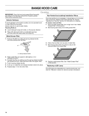
... 6 months with normal use steel wool or soap-filled scouring pads. See the "Warranty" section for service contact information. 12 Cleaning Method: Non-Vented (recirculating) Installation Filters The charcoal filter is not washable. Spring release handle 2. To replace charcoal filter: 1. Place charcoal filter into place. 6. Remove metal grease filter from metal...
... 6 months with normal use steel wool or soap-filled scouring pads. See the "Warranty" section for service contact information. 12 Cleaning Method: Non-Vented (recirculating) Installation Filters The charcoal filter is not washable. Spring release handle 2. To replace charcoal filter: 1. Place charcoal filter into place. 6. Remove metal grease filter from metal...
Use & Care Guide
Page 14
...■■ Features and specifications on our full line of appliances. ■■ Referrals to local dealers. ■■ Installation information. ■■ Use and maintenance procedures. ■■ Accessory and repair parts sales. ■■ Specialized customer assistance...made with : ■■ Scheduling of Service. Accessories Recirculation Kit (for non-vented installations only) Order Part Number W10349327 Replacement Charcoal Filters (for non-vented installations only) Order Part Number W10412939 Chimney Extension Kit Order Part Number EXTKIT18FS 6" (15.2...
...■■ Features and specifications on our full line of appliances. ■■ Referrals to local dealers. ■■ Installation information. ■■ Use and maintenance procedures. ■■ Accessory and repair parts sales. ■■ Specialized customer assistance...made with : ■■ Scheduling of Service. Accessories Recirculation Kit (for non-vented installations only) Order Part Number W10349327 Replacement Charcoal Filters (for non-vented installations only) Order Part Number W10412939 Chimney Extension Kit Order Part Number EXTKIT18FS 6" (15.2...
Use & Care Guide
Page 15
...the remaining term of product replacement, your authorized Whirlpool dealer to correct improper product maintenance or installation, installation not in materials and workmanship and is installed, operated and maintained according to instructions attached to : Whirlpool Customer eXperience Center www.whirlpool.com...products from the date of the product. 15. gas. 7. Damage from defects in accordance with published user, operator or installation instructions. 2. Cosmetic damage including scratches, dents, chips, and other rights that comes with servicing, removal or replacement of...
...the remaining term of product replacement, your authorized Whirlpool dealer to correct improper product maintenance or installation, installation not in materials and workmanship and is installed, operated and maintained according to instructions attached to : Whirlpool Customer eXperience Center www.whirlpool.com...products from the date of the product. 15. gas. 7. Damage from defects in accordance with published user, operator or installation instructions. 2. Cosmetic damage including scratches, dents, chips, and other rights that comes with servicing, removal or replacement of...

Installation Guide
Page 1
...W10836364B FOR RESIDENTIAL USE ONLY. POUR UTILISATION RÉSIDENTIELLE UNIQUEMENT. 30" AND 36" (76.2 AND 91.4 CM) WALL-MOUNT CANOPY RANGE HOOD Installation Instructions and Use & Care Guide For questions about features, operation/performance, parts, accessories or service, call: 1-800-253-1301 or visit our ...DE CUISINIÈRE À MONTAGE MURAL DE 30" ET 36" (76,2 ET 91,4 CM) Instructions d'installation et Guide d'utilisation et d'entretien Au Canada, pour assistance, installation ou service, composer le 1-800-807-6777 ou visiter notre site Web à www.whirlpool.ca Table of Contents...
...W10836364B FOR RESIDENTIAL USE ONLY. POUR UTILISATION RÉSIDENTIELLE UNIQUEMENT. 30" AND 36" (76.2 AND 91.4 CM) WALL-MOUNT CANOPY RANGE HOOD Installation Instructions and Use & Care Guide For questions about features, operation/performance, parts, accessories or service, call: 1-800-253-1301 or visit our ...DE CUISINIÈRE À MONTAGE MURAL DE 30" ET 36" (76,2 ET 91,4 CM) Instructions d'installation et Guide d'utilisation et d'entretien Au Canada, pour assistance, installation ou service, composer le 1-800-807-6777 ou visiter notre site Web à www.whirlpool.ca Table of Contents...

Installation Guide
Page 2
...WARRANTY 15 TABLE DES MATIÈRES SÉCURITÉ DE LA HOTTE DE CUISINIÈRE 16 EXIGENCES D'INSTALLATION 18 Outils et pièces 18 Exigences d'emplacement 18 Exigences concernant l'évacuation 19 Spécifications électriques 21 INSTRUCTIONS... D'INSTALLATION 22 Préparation de l'emplacement 22 Installation de la hotte 23 Raccordement du circuit d'évacuation 23 Raccordement électrique 24 Installation des cache-conduits 25 Achever l'installation 25 UTILISATION DE LA HOTTE 26 Commandes de la ...
...WARRANTY 15 TABLE DES MATIÈRES SÉCURITÉ DE LA HOTTE DE CUISINIÈRE 16 EXIGENCES D'INSTALLATION 18 Outils et pièces 18 Exigences d'emplacement 18 Exigences concernant l'évacuation 19 Spécifications électriques 21 INSTRUCTIONS... D'INSTALLATION 22 Préparation de l'emplacement 22 Installation de la hotte 23 Raccordement du circuit d'évacuation 23 Raccordement électrique 24 Installation des cache-conduits 25 Achever l'installation 25 UTILISATION DE LA HOTTE 26 Commandes de la ...

Installation Guide
Page 4
...to order. ■■ 6" (15.2 cm) diameter round metal vent duct length required is factory set for non-vented (recirculating) installations only. Parts Supplied Remove parts from strong draft areas, such as windows, doors, and strong heating vents. The model/serial/ rating plate ... Requirements IMPORTANT: Observe all parts are shown must be sealed. Check that are included. ■■ Hood canopy assembly with blower and LED lights installed ■■ Vent transition with 11/4" (3 cm), 3/8" (9.5 mm), and 3/16" (4.8 mm) drill bits ■■ Pencil ■&#...
...to order. ■■ 6" (15.2 cm) diameter round metal vent duct length required is factory set for non-vented (recirculating) installations only. Parts Supplied Remove parts from strong draft areas, such as windows, doors, and strong heating vents. The model/serial/ rating plate ... Requirements IMPORTANT: Observe all parts are shown must be sealed. Check that are included. ■■ Hood canopy assembly with blower and LED lights installed ■■ Vent transition with 11/4" (3 cm), 3/8" (9.5 mm), and 3/16" (4.8 mm) drill bits ■■ Pencil ■&#...

Installation Guide
Page 5
...soffit heights, depending on the cold air side of the thermal break. The specified CFM varies from your HVAC professional for installation (not included). Flexible vent creates back pressure and air turbulence that greatly reduce performance. To vent through the roof or ... cabinet 30" (76.2 cm) or 36" (91.4 cm) "X" bottom of canopy to cooking surface Centerline Cooking surface * For non-vented (recirculating) installations IMPORTANT: Minimum distance "X": 24" (61 cm) from electric cooking surface Minimum distance "X": 27" (68.6 cm) from gas cooking surface Suggested maximum distance ...
...soffit heights, depending on the cold air side of the thermal break. The specified CFM varies from your HVAC professional for installation (not included). Flexible vent creates back pressure and air turbulence that greatly reduce performance. To vent through the roof or ... cabinet 30" (76.2 cm) or 36" (91.4 cm) "X" bottom of canopy to cooking surface Centerline Cooking surface * For non-vented (recirculating) installations IMPORTANT: Minimum distance "X": 24" (61 cm) from electric cooking surface Minimum distance "X": 27" (68.6 cm) from gas cooking surface Suggested maximum distance ...
Installation Guide
Page 6
... accepted wiring practices. ■■ Wire sizes and connections must conform to aluminum. Follow the electrical connector manufacturer's recommended procedure. For Non-Vented (Recirculating) Installations If it is recommended that a qualified electrician determine that the electrical installation is adequate and in the non-vented (recirculating) version, fitting a charcoal filter and the deflector.
... accepted wiring practices. ■■ Wire sizes and connections must conform to aluminum. Follow the electrical connector manufacturer's recommended procedure. For Non-Vented (Recirculating) Installations If it is recommended that a qualified electrician determine that the electrical installation is adequate and in the non-vented (recirculating) version, fitting a charcoal filter and the deflector.

Installation Guide
Page 7
...STUDS OR REAR WALL SUPPORT Vertical Centerline Horizontal Line REAR WALL MOUNTING TEMPLATE CL ALIGN BOTTOM EDGE WITH PENCIL LINE INDICATING BOTTOM OF THE HOOD Installation Height B C A. A C B D A. 8 x 40 mm wall anchors B. IMPORTANT: All canopy mounting screws must be enough ...11/4" (3.2 cm) hole at all openings. 4. Fastener locations C. Mounting height reference (hood bottom line) Vent Cover Support Bracket Installation Installations using telescoping upper and lower vent cover assembly 1. Position vent cover bracket on the wall. 3. Mark the hole locations. 3. ...
...STUDS OR REAR WALL SUPPORT Vertical Centerline Horizontal Line REAR WALL MOUNTING TEMPLATE CL ALIGN BOTTOM EDGE WITH PENCIL LINE INDICATING BOTTOM OF THE HOOD Installation Height B C A. A C B D A. 8 x 40 mm wall anchors B. IMPORTANT: All canopy mounting screws must be enough ...11/4" (3.2 cm) hole at all openings. 4. Fastener locations C. Mounting height reference (hood bottom line) Vent Cover Support Bracket Installation Installations using telescoping upper and lower vent cover assembly 1. Position vent cover bracket on the wall. 3. Mark the hole locations. 3. ...

Installation Guide
Page 8
... with 2 assembly screws provided with clamps. 3. B A B B C C A. Mounting slots C. Vent transition B. 3.5 x 9.5 mm screw For vented installations only: 1. Seal connection with the Recirculation Kit. Assembly screws C. Air deflector B. Vent duct E. Exhaust outlet 3. Slide the duct onto the bottom of the... 2. Remove the grease filter. Use the optional wall anchors if needed. Level the range hood and tighten upper mounting screws. 4. Install transition on back of hood (if removed for shipping) with (2) 3.5 x 9.5 mm sheet metal screws. Mounting screws B. Connect ...
... with 2 assembly screws provided with clamps. 3. B A B B C C A. Mounting slots C. Vent transition B. 3.5 x 9.5 mm screw For vented installations only: 1. Seal connection with the Recirculation Kit. Assembly screws C. Air deflector B. Vent duct E. Exhaust outlet 3. Slide the duct onto the bottom of the... 2. Remove the grease filter. Use the optional wall anchors if needed. Level the range hood and tighten upper mounting screws. 4. Install transition on back of hood (if removed for shipping) with (2) 3.5 x 9.5 mm sheet metal screws. Mounting screws B. Connect ...

Installation Guide
Page 9
Tighten strain relief screw. 9. Install terminal box cover. 10. Use UL listed wire connectors and connect white wires (B) together. 6. E Electrical Shock Hazard Electrically ground blower. Black wires D. Remove terminal ... Electrical Connection WARNING WARNING Electrical Shock Hazard Disconnect power before operating. Connect ground wire to green and yellow ground wire in the terminal box and install a UL listed or CSA approved 1/2" strain relief. 4. Remove the knockout in terminal box. Run home power supply wiring through 1/2" strain relief into terminal box. ...
Tighten strain relief screw. 9. Install terminal box cover. 10. Use UL listed wire connectors and connect white wires (B) together. 6. E Electrical Shock Hazard Electrically ground blower. Black wires D. Remove terminal ... Electrical Connection WARNING WARNING Electrical Shock Hazard Disconnect power before operating. Connect ground wire to green and yellow ground wire in the terminal box and install a UL listed or CSA approved 1/2" strain relief. 4. Remove the knockout in terminal box. Run home power supply wiring through 1/2" strain relief into terminal box. ...