

Installation Instructions
Page 1
.... This symbol alerts you to reduce the chance of Contents MICROWAVE HOOD COMBINATION SAFETY 1 INSTALLATION REQUIREMENTS 2 Tools and Parts 2 Remove Cardboard Template 2 Location Requirements 2 Product Dimensions 3 Electrical Requirements 3 INSTALLATION INSTRUCTIONS 4 Remove Mounting Plate 4 Rotate Blower Motor 4 Locate Wall Stud(s 6 Mark Rear Wall 7 Drill Holes in these installation instructions. The appearance of...
.... This symbol alerts you to reduce the chance of Contents MICROWAVE HOOD COMBINATION SAFETY 1 INSTALLATION REQUIREMENTS 2 Tools and Parts 2 Remove Cardboard Template 2 Location Requirements 2 Product Dimensions 3 Electrical Requirements 3 INSTALLATION INSTRUCTIONS 4 Remove Mounting Plate 4 Rotate Blower Motor 4 Locate Wall Stud(s 6 Mark Rear Wall 7 Drill Holes in these installation instructions. The appearance of...

Installation Instructions
Page 2
..." socket wrench (or box wrench) for 1/4" x 2" lag screws ■ 1½" (3.8 cm) diam. The location must be included. See "Installation Dimensions" illustration. ■ Minimum one 2" x 4" (50.8 x 101.6 mm) wood wall stud and minimum 3/8" (10 mm) thickness drywall or plaster/lath...of installation. Washers (2) D. Special Requirements For Wall Venting Installation Only: ■ Cutout must provide: ■ Minimum installation dimensions. Sheet metal screws (2) G. The piece inside upper cabinet. Read and follow the instructions provided with your builder or cabinet ...
..." socket wrench (or box wrench) for 1/4" x 2" lag screws ■ 1½" (3.8 cm) diam. The location must be included. See "Installation Dimensions" illustration. ■ Minimum one 2" x 4" (50.8 x 101.6 mm) wood wall stud and minimum 3/8" (10 mm) thickness drywall or plaster/lath...of installation. Washers (2) D. Special Requirements For Wall Venting Installation Only: ■ Cutout must provide: ■ Minimum installation dimensions. Sheet metal screws (2) G. The piece inside upper cabinet. Read and follow the instructions provided with your builder or cabinet ...

Installation Instructions
Page 3
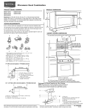
... prong outlet. Do not use an adapter. Grounded 3 prong outlet *30" (76.2 cm) is properly installed and grounded. Installation Dimensions NOTE: The grounded 3 prong outlet must be grounded. SAVE THESE INSTRUCTIONS 3 Consult a qualified electrician or serviceman if the grounding instructions are...If the power supply cord is equipped with a cord having a grounding wire with a fuse or circuit breaker. A. 2" x 4" wall stud B. Product Dimensions 17¹⁄₄" (43.8 cm) 16¹⁄₄" (41.3 cm) (411.06¹c⁄₈m") 29⁷⁄₈" (76...
... prong outlet. Do not use an adapter. Grounded 3 prong outlet *30" (76.2 cm) is properly installed and grounded. Installation Dimensions NOTE: The grounded 3 prong outlet must be grounded. SAVE THESE INSTRUCTIONS 3 Consult a qualified electrician or serviceman if the grounding instructions are...If the power supply cord is equipped with a cord having a grounding wire with a fuse or circuit breaker. A. 2" x 4" wall stud B. Product Dimensions 17¹⁄₄" (43.8 cm) 16¹⁄₄" (41.3 cm) (411.06¹c⁄₈m") 29⁷⁄₈" (76...

Installation Instructions
Page 7
...;⁄₈" (35.9 cm) from the centerline. 5. Centerline 2. Set the mounting plate aside. Cut a 3/4" (19 mm) hole in one 1/4-20 x 3" round-head bolt with the dimensions described in "Locate Wall Stud(s)" section. 7 Using a keyhole saw, cut out the venting cutout area. or if both end holes are over wall studs, use...
...;⁄₈" (35.9 cm) from the centerline. 5. Centerline 2. Set the mounting plate aside. Cut a 3/4" (19 mm) hole in one 1/4-20 x 3" round-head bolt with the dimensions described in "Locate Wall Stud(s)" section. 7 Using a keyhole saw, cut out the venting cutout area. or if both end holes are over wall studs, use...

Installation Instructions
Page 8
... plate, making sure it fits inside the frame, against the upper cabinet bottom. Remove all lag screws and bolts. Make sure the 10" (25.4 cm) dimension from the back of the mounting plate. Leave enough space for the toggle nuts to go through the drywall, and finger tighten the bolt to...
... plate, making sure it fits inside the frame, against the upper cabinet bottom. Remove all lag screws and bolts. Make sure the 10" (25.4 cm) dimension from the back of the mounting plate. Leave enough space for the toggle nuts to go through the drywall, and finger tighten the bolt to...
Dimension Guide
Page 1
... piece, at least 3" (7.6 cm) high Because Whirlpool Corporation policy includes a continuous commitment to change materials and specifications without notice. Specifications subject to improve Dimensions are for each vent piece used . Rectangular to round transition piece: 3 " x 10" to 6" = 5 ft (8.3 x 25.4 cm to ... cm) min. 30" (76.2 cm) min. 30" (76.2 cm) typical* 12" (30.5 cm) min. 14" (35.6 cm) max. Exact dimensions may vary depending on type of vent. Roof cap B. 6" (15.2 cm) min. Instructions packed with a fuse or circuit breaker. diameter round vent C. or 20...
... piece, at least 3" (7.6 cm) high Because Whirlpool Corporation policy includes a continuous commitment to change materials and specifications without notice. Specifications subject to improve Dimensions are for each vent piece used . Rectangular to round transition piece: 3 " x 10" to 6" = 5 ft (8.3 x 25.4 cm to ... cm) min. 30" (76.2 cm) min. 30" (76.2 cm) typical* 12" (30.5 cm) min. 14" (35.6 cm) max. Exact dimensions may vary depending on type of vent. Roof cap B. 6" (15.2 cm) min. Instructions packed with a fuse or circuit breaker. diameter round vent C. or 20...
