
Installation Instructions
Page 1
... you to Wall 8 Prepare Upper Cabinet 8 Install Damper Assembly 9 Install the Microwave Oven 9 Complete Installation 10 VENTING DESIGN SPECIFICATIONS 11 ASSISTANCE 12 Replacement Parts 12 Accessories 12 MICROWAVE HOOD COMBINATION SAFETY Your safety and the safety of Contents MICROWAVE HOOD COMBINATION SAFETY 1 INSTALLATION REQUIREMENTS 2 Tools and Parts 2 Remove Cardboard Template 2 Location Requirements 2 Product Dimensions 3 Electrical Requirements 3 INSTALLATION INSTRUCTIONS 4 Remove Mounting Plate 4 Rotate Blower Motor 4 Locate Wall Stud(s 6 Mark Rear Wall 7 Drill...
... you to Wall 8 Prepare Upper Cabinet 8 Install Damper Assembly 9 Install the Microwave Oven 9 Complete Installation 10 VENTING DESIGN SPECIFICATIONS 11 ASSISTANCE 12 Replacement Parts 12 Accessories 12 MICROWAVE HOOD COMBINATION SAFETY Your safety and the safety of Contents MICROWAVE HOOD COMBINATION SAFETY 1 INSTALLATION REQUIREMENTS 2 Tools and Parts 2 Remove Cardboard Template 2 Location Requirements 2 Product Dimensions 3 Electrical Requirements 3 INSTALLATION INSTRUCTIONS 4 Remove Mounting Plate 4 Rotate Blower Motor 4 Locate Wall Stud(s 6 Mark Rear Wall 7 Drill...

Installation Instructions
Page 2
... User Instructions.) NOTE: Depending on model, charcoal filters may be sure to back of microwave oven) Cardboard template (part of packaging) Aluminum grease filters Charcoal filters (Depending on model, aluminum grease filter and charcoal filter may not be installed. The location must be free of the cardboard packaging. 2. Special Requirements For Wall Venting Installation Only: ■ Cutout must provide: ■ Minimum installation dimensions. Sheet metal screws (2) G. Damper assembly (for 1/4" x 2" lag screws ■ 1½" (3.8 cm) diam. Remove Cardboard Template...
... User Instructions.) NOTE: Depending on model, charcoal filters may be sure to back of microwave oven) Cardboard template (part of packaging) Aluminum grease filters Charcoal filters (Depending on model, aluminum grease filter and charcoal filter may not be installed. The location must be free of the cardboard packaging. 2. Special Requirements For Wall Venting Installation Only: ■ Cutout must provide: ■ Minimum installation dimensions. Sheet metal screws (2) G. Damper assembly (for 1/4" x 2" lag screws ■ 1½" (3.8 cm) diam. Remove Cardboard Template...

Installation Instructions
Page 3
... INSTRUCTIONS ■ For all governing codes and ordinances. Do not use an adapter. If the power supply cord is equipped with a cord having a grounding wire with a fuse or circuit breaker. upper cabinet and side cabinet depth Electrical Shock Hazard Plug into an outlet that is properly grounded. Do not use an extension cord. Required: ■ A 120 Volt, 60 Hz, AC only, 15- The microwave oven is...
... INSTRUCTIONS ■ For all governing codes and ordinances. Do not use an adapter. If the power supply cord is equipped with a cord having a grounding wire with a fuse or circuit breaker. upper cabinet and side cabinet depth Electrical Shock Hazard Plug into an outlet that is properly grounded. Do not use an extension cord. Required: ■ A 120 Volt, 60 Hz, AC only, 15- The microwave oven is...

Installation Instructions
Page 4
... 3. 7. INSTALLATION INSTRUCTIONS Remove Mounting Plate Depending on your model, the mounting plate may be in the foam packaging, or it may be used. Reattach damper plate. Slots 8. NOTE: To avoid possible damage to top of microwave oven, and lower blower motor back into the slots in recessed holes) D A. Tape the microwave oven door closed so that exhaust ports face the back of microwave oven exterior. Wall Venting Installation Only 1. Remove screws attaching damper plate to the work surface, cover...
... 3. 7. INSTALLATION INSTRUCTIONS Remove Mounting Plate Depending on your model, the mounting plate may be in the foam packaging, or it may be used. Reattach damper plate. Slots 8. NOTE: To avoid possible damage to top of microwave oven, and lower blower motor back into the slots in recessed holes) D A. Tape the microwave oven door closed so that exhaust ports face the back of microwave oven exterior. Wall Venting Installation Only 1. Remove screws attaching damper plate to the work surface, cover...

Installation Instructions
Page 5
... tighten screws. Make sure damper plate tabs are inserted into microwave oven. Damper plate B. Secure damper plate with 2 screws removed in Step 3 cannot be poor. Repeat Step 3 from "Wall Venting Installation Only." 5. A 6. Reattach blower motor to the microwave oven. 7. Exhaust port IMPORTANT: If blower motor is not correctly oriented, the 2 screws removed in Step 1 of "Wall Venting Installation Only." Slots 8. Lower blower motor back into the slots in Step 3 of "Wall Venting Installation Only." 5 Reattach damper plate. D A. NOTE: If blower motor...
... tighten screws. Make sure damper plate tabs are inserted into microwave oven. Damper plate B. Secure damper plate with 2 screws removed in Step 3 cannot be poor. Repeat Step 3 from "Wall Venting Installation Only." 5. A 6. Reattach blower motor to the microwave oven. 7. Exhaust port IMPORTANT: If blower motor is not correctly oriented, the 2 screws removed in Step 1 of "Wall Venting Installation Only." Slots 8. Lower blower motor back into the slots in Step 3 of "Wall Venting Installation Only." 5 Reattach damper plate. D A. NOTE: If blower motor...

Installation Instructions
Page 6
... of preferred installation configurations with the mounting plate. Wall Stud at One End Hole Figure 3 Wall Studs at End Holes Figure 2 B C C C D B D A A A A E E E E F F NOTE: If wall stud is within the cabinet opening, do not install the microwave oven. 1. See illustrations in "Possible Wall Stud Configurations." 2. Holes for lag screws E. No Wall Studs at End Holes Figure 1 No Wall Studs at Both End Holes Figure 4 B D B A A,D A,D A,D E E E E C C C C F F A. Using a stud finder, locate the...
... of preferred installation configurations with the mounting plate. Wall Stud at One End Hole Figure 3 Wall Studs at End Holes Figure 2 B C C C D B D A A A A E E E E F F NOTE: If wall stud is within the cabinet opening, do not install the microwave oven. 1. See illustrations in "Possible Wall Stud Configurations." 2. Holes for lag screws E. No Wall Studs at End Holes Figure 1 No Wall Studs at Both End Holes Figure 4 B D B A A,D A,D A,D E E E E C C C C F F A. Using a stud finder, locate the...

Installation Instructions
Page 7
..., lower the cardboard template so that the end holes are properly marked. Cut a 3/4" (19 mm) hole in one 1/4-20 x 3" round-head bolt with toggle nut; A A. Rear wall B. With the support tabs facing forward (see illustrations in "Locate Wall Stud(s)" section), align the mounting plate center markers to figures 1 and 2 in "Possible Wall Stud Configurations" in "Locate Wall Stud(s)" section. 7 Wall Venting Installation Only Upper cabinet bottom ³...
..., lower the cardboard template so that the end holes are properly marked. Cut a 3/4" (19 mm) hole in one 1/4-20 x 3" round-head bolt with toggle nut; A A. Rear wall B. With the support tabs facing forward (see illustrations in "Locate Wall Stud(s)" section), align the mounting plate center markers to figures 1 and 2 in "Possible Wall Stud Configurations" in "Locate Wall Stud(s)" section. 7 Wall Venting Installation Only Upper cabinet bottom ³...

Installation Instructions
Page 8
... end hole that it is level. 4. Spring toggle nut 3. Position mounting plate on the bolt from the back of mounting plate, making sure it fits inside the frame, against the upper cabinet bottom. The template has trim lines to use as guides. ■ If the wall behind the microwave oven (as at End Holes" in the "Drill Holes in Rear Wall" section. 7. Start a toggle nut on the...
... end hole that it is level. 4. Spring toggle nut 3. Position mounting plate on the bolt from the back of mounting plate, making sure it fits inside the frame, against the upper cabinet bottom. The template has trim lines to use as guides. ■ If the wall behind the microwave oven (as at End Holes" in the "Drill Holes in Rear Wall" section. 7. Start a toggle nut on the...

Installation Instructions
Page 9
...: The control side of mounting plate. Damper assembly C. Metal cabinet B. Check that the damper blade hinge is metal, the supply cord bushing needs to be installed around the supply cord hole, as shown. Secure damper assembly with 2 sheet metal screws. With front of microwave oven still tilted, thread power supply cord through the wall, make sure the damper assembly fits easily into the vent in the bottom of microwave oven B. Place a washer on the template. This...
...: The control side of mounting plate. Damper assembly C. Metal cabinet B. Check that the damper blade hinge is metal, the supply cord bushing needs to be installed around the supply cord hole, as shown. Secure damper assembly with 2 sheet metal screws. With front of microwave oven still tilted, thread power supply cord through the wall, make sure the damper assembly fits easily into the vent in the bottom of microwave oven B. Place a washer on the template. This...

Installation Instructions
Page 10
.... ■ See the User Instructions for troubleshooting information. Long tab F. Do not use an extension cord. Reconnect power. 4. Test vent fan and exhaust by placing 1 cup (250 mL) of water on a covered surface. 8. Replace the fuse or reset the circuit breaker. Using 2 or more people, lift microwave oven off of the damper plate. Tighten bolts until there is plugged into microwave oven. Vent B. Refer to the User Instructions for future use. 10 Damper assembly C. Damper plate Electrical Shock Hazard Plug...
.... ■ See the User Instructions for troubleshooting information. Long tab F. Do not use an extension cord. Reconnect power. 4. Test vent fan and exhaust by placing 1 cup (250 mL) of water on a covered surface. 8. Replace the fuse or reset the circuit breaker. Using 2 or more people, lift microwave oven off of the damper plate. Tighten bolts until there is plugged into microwave oven. Vent B. Refer to the User Instructions for future use. 10 Damper assembly C. Damper plate Electrical Shock Hazard Plug...
Installation Instructions
Page 11
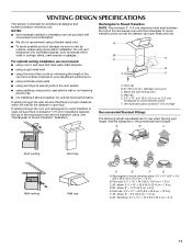
... venting installation, we recommend: ■ using roof or wall caps that have back draft dampers ■ using a rigid metal vent ■ using the most direct route by minimizing the length of the vent and number of elbows to provide efficient performance ■ using uniformly sized vents ■ using duct tape to vent air outside, unless using a flexible metal vent. ■ To avoid possible product damage, be sure that the damper can open...
... venting installation, we recommend: ■ using roof or wall caps that have back draft dampers ■ using a rigid metal vent ■ using the most direct route by minimizing the length of the vent and number of elbows to provide efficient performance ■ using uniformly sized vents ■ using duct tape to vent air outside, unless using a flexible metal vent. ■ To avoid possible product damage, be sure that the damper can open...

Installation Instructions
Page 12
... ft (42.7 m) for equivalent lengths. Recommended Vent Length A 3¹⁄₄" x 10" (8.3 x 25.4 cm) rectangular or 6" (15.2 cm) round vent should be found on the model and serial number plate, which is located behind the door. ■ Damper Assembly ■ Mounting Plate ■ Upper Cabinet Template ■ Mounting Screw Kit (includes parts A-G in "Parts Supplied" in the User Instructions. When you call us at our toll free number or visit our website listed in the User Instructions...
... ft (42.7 m) for equivalent lengths. Recommended Vent Length A 3¹⁄₄" x 10" (8.3 x 25.4 cm) rectangular or 6" (15.2 cm) round vent should be found on the model and serial number plate, which is located behind the door. ■ Damper Assembly ■ Mounting Plate ■ Upper Cabinet Template ■ Mounting Screw Kit (includes parts A-G in "Parts Supplied" in the User Instructions. When you call us at our toll free number or visit our website listed in the User Instructions...
Owners Manual
Page 1
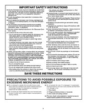
...manual and on your model and serial number located on the front facing of others . SAVE THESE INSTRUCTIONS W10336688A MICROWAVE HOOD COMBINATION USER INSTRUCTIONS THANK YOU for example, closed glass jars - Puede encontrar su número de modelo y de serie en la etiqueta ubicada en la parte frontal de la abertura del horno de microondas...Connect only to reduce the chance of burns, electric shock, fire, injury to persons, or exposure to explode and should experience a problem not covered in the microwave oven. ■ The microwave oven must be killed or seriously injured if you...
...manual and on your model and serial number located on the front facing of others . SAVE THESE INSTRUCTIONS W10336688A MICROWAVE HOOD COMBINATION USER INSTRUCTIONS THANK YOU for example, closed glass jars - Puede encontrar su número de modelo y de serie en la etiqueta ubicada en la parte frontal de la abertura del horno de microondas...Connect only to reduce the chance of burns, electric shock, fire, injury to persons, or exposure to explode and should experience a problem not covered in the microwave oven. ■ The microwave oven must be killed or seriously injured if you...
Owners Manual
Page 2
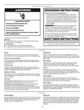
... operation. ■ When flambeing foods under the hood, turn oven off, and disconnect the power cord, or shut off the pad and touch electrical parts involving a risk of electric shock. ■ Suitable for use paper products when appliance is operated in convection, combination, grill or "PAN BROWN" mode (on models with the door open since open-door operation can burn off power at the fuse or circuit breaker panel. - Corrosive cleaning agents, such as they may damage the filter...
... operation. ■ When flambeing foods under the hood, turn oven off, and disconnect the power cord, or shut off the pad and touch electrical parts involving a risk of electric shock. ■ Suitable for use paper products when appliance is operated in convection, combination, grill or "PAN BROWN" mode (on models with the door open since open-door operation can burn off power at the fuse or circuit breaker panel. - Corrosive cleaning agents, such as they may damage the filter...
Owners Manual
Page 3
... Setup Vent Timer, Light Timer, Filter Reset, Sound On/Off, Scroll Speed, Demo Mode and Language (English or French) (on some models) functions. 3 Touch Options or Setup control to follow these instructions can be changed. or P.M. See "Microwave Oven Care" section. Programming tones may be turned off, or all tones (including end-of-function signals) may be adjusted. Touch the Start control to practice using the Vent Fan control. or 20-amp electrical supply with A.M. Do not use an extension cord. Vent Timer (on . Electrical...
... Setup Vent Timer, Light Timer, Filter Reset, Sound On/Off, Scroll Speed, Demo Mode and Language (English or French) (on some models) functions. 3 Touch Options or Setup control to follow these instructions can be changed. or P.M. See "Microwave Oven Care" section. Programming tones may be turned off, or all tones (including end-of-function signals) may be adjusted. Touch the Start control to practice using the Vent Fan control. or 20-amp electrical supply with A.M. Do not use an extension cord. Vent Timer (on . Electrical...
Owners Manual
Page 4
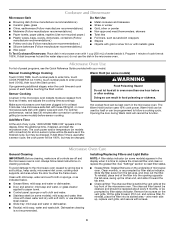
...%), touch number pads to reset filter status. ■ Grease filters: Grease filters are off and the microwave oven is cool. Remove two screws on cleaning products. To reinstall, place the filter into the opening opposite the tab area, swing up , replace vent grille, and secure with 1 cup (250 mL) of microwave oven. The Warm Hold function uses 10% cook power. Always follow a cooking cycle. See "Settings" section to enter power level (10-90), then touch the Start control. Microwave Oven Use For list of...
...%), touch number pads to reset filter status. ■ Grease filters: Grease filters are off and the microwave oven is cool. Remove two screws on cleaning products. To reinstall, place the filter into the opening opposite the tab area, swing up , replace vent grille, and secure with 1 cup (250 mL) of microwave oven. The Warm Hold function uses 10% cook power. Always follow a cooking cycle. See "Settings" section to enter power level (10-90), then touch the Start control. Microwave Oven Use For list of...
Owners Manual
Page 5
... below is being started. Make sure Demo Mode (on during microwave oven operation to inside of the microwave oven, under the bulb cover, and is set properly. Replacement Parts Cleaning Supplies ■ Glide tray ■ Glide tray support ■ Cooking rack ■ Rack clip ■ Rack support ■ Grease filter ■ Charcoal filter ■ Cooktop light bulb ■ Cavity light bulb ■ Heavy Duty Degreaser ■ All-Purpose Appliance Cleaner ■ Stainless Steel Cleaner and Polish 5 Remove bulb cover screw, and open the bulb cover. On some models), which may...
... below is being started. Make sure Demo Mode (on during microwave oven operation to inside of the microwave oven, under the bulb cover, and is set properly. Replacement Parts Cleaning Supplies ■ Glide tray ■ Glide tray support ■ Cooking rack ■ Rack clip ■ Rack support ■ Grease filter ■ Charcoal filter ■ Cooktop light bulb ■ Cavity light bulb ■ Heavy Duty Degreaser ■ All-Purpose Appliance Cleaner ■ Stainless Steel Cleaner and Polish 5 Remove bulb cover screw, and open the bulb cover. On some models), which may...
Owners Manual
Page 6
... installation, installation not in accordance with the product, Maytag will pay for product service if your major appliance, to replace or repair house fuses, or to instruct you can find your major appliance if it was purchased. Cosmetic damage, including scratches, dents, chips or other than normal, single-family household use of the microwave range hood and that existed when this User Instructions and model number information...
... installation, installation not in accordance with the product, Maytag will pay for product service if your major appliance, to replace or repair house fuses, or to instruct you can find your major appliance if it was purchased. Cosmetic damage, including scratches, dents, chips or other than normal, single-family household use of the microwave range hood and that existed when this User Instructions and model number information...


