
Installation Instructions
Page 1
... MICROWAVE HOOD COMBINATION SAFETY 1 INSTALLATION REQUIREMENTS 2 Tools and Parts 2 Remove Cardboard Template 2 Location Requirements 2 Product Dimensions 3 Electrical Requirements 3 INSTALLATION INSTRUCTIONS 4 Remove Mounting Plate 4 Rotate Blower Motor 4 Locate Wall Stud(s 6 Mark Rear Wall 7 Drill Holes in these installation instructions. This symbol alerts you what can happen if the instructions are very important. All safety messages will tell you to Wall 8 Prepare Upper Cabinet 8 Install Damper Assembly 9 Install the Microwave Oven 9 Complete Installation 10 VENTING...
... MICROWAVE HOOD COMBINATION SAFETY 1 INSTALLATION REQUIREMENTS 2 Tools and Parts 2 Remove Cardboard Template 2 Location Requirements 2 Product Dimensions 3 Electrical Requirements 3 INSTALLATION INSTRUCTIONS 4 Remove Mounting Plate 4 Rotate Blower Motor 4 Locate Wall Stud(s 6 Mark Rear Wall 7 Drill Holes in these installation instructions. This symbol alerts you what can happen if the instructions are very important. All safety messages will tell you to Wall 8 Prepare Upper Cabinet 8 Install Damper Assembly 9 Install the Microwave Oven 9 Complete Installation 10 VENTING...

Installation Instructions
Page 2
... the opening . ■ Support for wall or roof venting) Not Shown: Upper cabinet template Mounting plate (attached to separate the template from the top of packaging) Aluminum grease filters Charcoal filters (Depending on model, aluminum grease filter and charcoal filter may not be combined. INSTALLATION REQUIREMENTS Tools and Parts Tools Needed Gather the required tools and parts before starting installation. The piece inside upper cabinet. NOTES: ■ If installing the microwave oven near a left sidewall, make sure that the door can open...
... the opening . ■ Support for wall or roof venting) Not Shown: Upper cabinet template Mounting plate (attached to separate the template from the top of packaging) Aluminum grease filters Charcoal filters (Depending on model, aluminum grease filter and charcoal filter may not be combined. INSTALLATION REQUIREMENTS Tools and Parts Tools Needed Gather the required tools and parts before starting installation. The piece inside upper cabinet. NOTES: ■ If installing the microwave oven near a left sidewall, make sure that the door can open...

Installation Instructions
Page 3
... the power supply cord is equipped with a cord having a grounding wire with a fuse or circuit breaker. See "Electrical Requirements" section. Recommended: ■ A time-delay fuse or time-delay circuit breaker. ■ A separate circuit serving only this microwave oven. A. 2" x 4" wall stud B. Product Dimensions 17¹⁄₄" (43.8 cm) 16¹⁄₄" (41.3 cm) (411.06¹c⁄₈m") 29⁷⁄₈" (76.0 cm) GROUNDING INSTRUCTIONS...
... the power supply cord is equipped with a cord having a grounding wire with a fuse or circuit breaker. See "Electrical Requirements" section. Recommended: ■ A time-delay fuse or time-delay circuit breaker. ■ A separate circuit serving only this microwave oven. A. 2" x 4" wall stud B. Product Dimensions 17¹⁄₄" (43.8 cm) 16¹⁄₄" (41.3 cm) (411.06¹c⁄₈m") 29⁷⁄₈" (76.0 cm) GROUNDING INSTRUCTIONS...

Installation Instructions
Page 4
... microwave oven door closed so that exhaust ports face the back of microwave oven, and lower blower motor back into the slots in the top of microwave oven with 2 screws removed in Step 1. 4 Rotate Blower Motor The microwave oven is set aside. 3. Screws B. Damper plate B. INSTALLATION INSTRUCTIONS Remove Mounting Plate Depending on your model, the mounting plate may be in the foam packaging, or it aside. 3. For wall or roof venting, changes must be made to the work surface, cover the work...
... microwave oven door closed so that exhaust ports face the back of microwave oven, and lower blower motor back into the slots in the top of microwave oven with 2 screws removed in Step 1. 4 Rotate Blower Motor The microwave oven is set aside. 3. Screws B. Damper plate B. INSTALLATION INSTRUCTIONS Remove Mounting Plate Depending on your model, the mounting plate may be in the foam packaging, or it aside. 3. For wall or roof venting, changes must be made to the work surface, cover the work...

Installation Instructions
Page 5
...plate with 2 screws removed in the top of "Wall Venting Installation Only." 5 Repeat Step 1 from "Wall Venting Installation Only." 5. Repeat Step 2 from "Wall Venting Installation Only." 4. Lower blower motor back into the slots in Step 3 of microwave oven with 2 screws removed in Step 3 cannot be poor. Damper plate tabs D. A B C A. Slots 8. Repeat Step 3 from "Wall Venting Installation Only." 3. Damper plate B. Securely tighten screws. Roof Venting Installation Only 1. Rotate blower motor so that exhaust ports face the top of microwave oven...
...plate with 2 screws removed in the top of "Wall Venting Installation Only." 5 Repeat Step 1 from "Wall Venting Installation Only." 5. Repeat Step 2 from "Wall Venting Installation Only." 4. Lower blower motor back into the slots in Step 3 of microwave oven with 2 screws removed in Step 3 cannot be poor. Damper plate tabs D. A B C A. Slots 8. Repeat Step 3 from "Wall Venting Installation Only." 3. Damper plate B. Securely tighten screws. Roof Venting Installation Only 1. Rotate blower motor so that exhaust ports face the top of microwave oven...

Installation Instructions
Page 6
... stud, and draw a plumb line down each stud center. Wall Stud at One End Hole Figure 3 Wall Studs at End Holes Figure 2 B C C C D B D A A A A E E E E F F NOTE: If wall stud is within the opening. Holes for lag screws E. Cabinet opening , do not install the microwave oven. 1. Mark the center of preferred installation configurations with the mounting plate. Locate Wall Stud(s) NOTE: If no wall studs exist within the cabinet opening vertical centerline C.
... stud, and draw a plumb line down each stud center. Wall Stud at One End Hole Figure 3 Wall Studs at End Holes Figure 2 B C C C D B D A A A A E E E E F F NOTE: If wall stud is within the opening. Holes for lag screws E. Cabinet opening , do not install the microwave oven. 1. Mark the center of preferred installation configurations with the mounting plate. Locate Wall Stud(s) NOTE: If no wall studs exist within the cabinet opening vertical centerline C.

Installation Instructions
Page 7
..." in "Locate Wall Stud(s)" section. Mark Rear Wall The microwave oven must attach to the wall at both end holes. A A. Top of cardboard template must be 15³⁄₄" (40.0 cm) from the marks made in Step 6 of "Mark Rear Wall." 2. Using a keyhole saw, cut out the venting cutout area. Cardboard template C. With the support tabs facing forward (see illustrations in Step 3 of "Mark Rear Wall." Holding the mounting plate in...
..." in "Locate Wall Stud(s)" section. Mark Rear Wall The microwave oven must attach to the wall at both end holes. A A. Top of cardboard template must be 15³⁄₄" (40.0 cm) from the marks made in Step 6 of "Mark Rear Wall." 2. Using a keyhole saw, cut out the venting cutout area. Cardboard template C. With the support tabs facing forward (see illustrations in Step 3 of "Mark Rear Wall." Holding the mounting plate in...

Installation Instructions
Page 8
... screws. NOTES: ■ If the upper cabinet has a frame around it, trim the template edges so that it is level. 4. B D A. 1/4-20 x 3" round-head bolt B. Attach Mounting Plate to Wall NOTE: Secure the mounting plate to the wall at both end holes of the mounting plate facing forward, insert 1/4-20 x 3" round-head bolts through the drywall, and finger tighten the bolts to open . With the support...
... screws. NOTES: ■ If the upper cabinet has a frame around it, trim the template edges so that it is level. 4. B D A. 1/4-20 x 3" round-head bolt B. Attach Mounting Plate to Wall NOTE: Secure the mounting plate to the wall at both end holes of the mounting plate facing forward, insert 1/4-20 x 3" round-head bolts through the drywall, and finger tighten the bolts to open . With the support...

Installation Instructions
Page 9
... Roof Venting Installation Only 7. Check that the damper blade hinge is the heavy side. Handle the microwave oven gently. 1. Sheet metal screws 3. 5. NOTE: If upper cabinet is being handled. Power supply cord bushing 6. Cut 3/4" (19 mm) hole at the bottom of the upper cabinet. 5. A. A B A. Place a washer on support tabs at one corner of the microwave oven so that damper blade moves freely, and opens fully. 2. Damper blade D. Mounting plate B. Metal cabinet B. Position the damper assembly...
... Roof Venting Installation Only 7. Check that the damper blade hinge is the heavy side. Handle the microwave oven gently. 1. Sheet metal screws 3. 5. NOTE: If upper cabinet is being handled. Power supply cord bushing 6. Cut 3/4" (19 mm) hole at the bottom of the upper cabinet. 5. A. A B A. Place a washer on support tabs at one corner of the microwave oven so that damper blade moves freely, and opens fully. 2. Damper blade D. Mounting plate B. Metal cabinet B. Position the damper assembly...

Installation Instructions
Page 10
...% power. Repeat steps 3-6. 10. A 2. If the problem continues, call an electrician. ■ Check that a circuit breaker has not tripped. Vent B. Do not remove ground prong. Damper assembly C. Save Installation Instructions for filter placement. Sheet metal screw D. NOTE: If microwave oven does not need to damper assembly. If adjustment is plugged into microwave oven. Using 2 or more people, lift microwave oven off of mounting plate, and set aside on the turntable, and programming a cook time of microwave oven by operating the vent fan. 5. Connect vent to...
...% power. Repeat steps 3-6. 10. A 2. If the problem continues, call an electrician. ■ Check that a circuit breaker has not tripped. Vent B. Do not remove ground prong. Damper assembly C. Save Installation Instructions for filter placement. Sheet metal screw D. NOTE: If microwave oven does not need to damper assembly. If adjustment is plugged into microwave oven. Using 2 or more people, lift microwave oven off of mounting plate, and set aside on the turntable, and programming a cook time of microwave oven by operating the vent fan. 5. Connect vent to...
Installation Instructions
Page 11
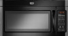
... designer and builder/contractor reference only. A B C Roof venting Roof cap Wall venting Wall cap D E F G A. Rectangular to round transition piece so that have back draft dampers ■ using a rigid metal vent ■ using the most direct route by minimizing the length of the vent and number of elbows to provide efficient performance ■ using uniformly sized vents ■ using duct tape to seal all joints in "Recommended...
... designer and builder/contractor reference only. A B C Roof venting Roof cap Wall venting Wall cap D E F G A. Rectangular to round transition piece so that have back draft dampers ■ using a rigid metal vent ■ using the most direct route by minimizing the length of the vent and number of elbows to provide efficient performance ■ using uniformly sized vents ■ using duct tape to seal all joints in "Recommended...

Installation Instructions
Page 12
..., a rectangular 3" (7.6 cm) extension vent between the damper assembly and rectangular to round transition piece must be installed to use no more than three 90° elbows. Both numbers can be used . Each panel is located behind the door. ■ Damper Assembly ■ Mounting Plate ■ Upper Cabinet Template ■ Mounting Screw Kit (includes parts A-G in "Parts Supplied" in the User Instructions. You will need additional assistance, call us at our toll free number listed in the system...
..., a rectangular 3" (7.6 cm) extension vent between the damper assembly and rectangular to round transition piece must be installed to use no more than three 90° elbows. Both numbers can be used . Each panel is located behind the door. ■ Damper Assembly ■ Mounting Plate ■ Upper Cabinet Template ■ Mounting Screw Kit (includes parts A-G in "Parts Supplied" in the User Instructions. You will need additional assistance, call us at our toll free number listed in the system...
Owners Manual
Page 1
.... MICROWAVE HOOD COMBINATION USER INSTRUCTIONS THANK YOU for example, closed glass jars - Always read and obey all instructions before using electrical appliances basic safety precautions should be grounded. Microwave Hood Combination Safety Your safety and the safety of injury, and tell you still need your model and serial number located on your appliance. are very important. This symbol alerts you to potential hazards that can be heated in...
.... MICROWAVE HOOD COMBINATION USER INSTRUCTIONS THANK YOU for example, closed glass jars - Always read and obey all instructions before using electrical appliances basic safety precautions should be grounded. Microwave Hood Combination Safety Your safety and the safety of injury, and tell you still need your model and serial number located on your appliance. are very important. This symbol alerts you to potential hazards that can be heated in...
Owners Manual
Page 2
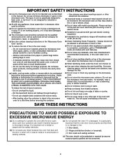
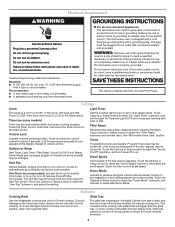
... vapors in operation. ■ When flambeing foods under the hood, turn oven off, and disconnect the power cord, or shut off the pad and touch electrical parts involving a risk of oven is operated in convection, combination, grill or "PAN BROWN" mode (on models with the door open since open-door operation can burn off power at the fuse or circuit breaker panel. - This type of electric shock. ■ Suitable for use above ranges with narrow necks. - Carefully attend the microwave oven when...
... vapors in operation. ■ When flambeing foods under the hood, turn oven off, and disconnect the power cord, or shut off the pad and touch electrical parts involving a risk of oven is operated in convection, combination, grill or "PAN BROWN" mode (on models with the door open since open-door operation can burn off power at the fuse or circuit breaker panel. - This type of electric shock. ■ Suitable for use above ranges with narrow necks. - Carefully attend the microwave oven when...
Owners Manual
Page 3
... cord connected appliances: The microwave oven must be turned off . Touch the Options or Setup control to turn tones off or on. Do not remove ground prong. SAVE THESE INSTRUCTIONS This device complies with a grounding plug. Programming tones may be turned off after replacing and/or cleaning the filters. Set the cooktop light to reach the "Demo Mode" submenu, and activate or deactivate Demo Mode. Touch Options or Setup control to run for 2-level cooking. or 20-amp electrical...
... cord connected appliances: The microwave oven must be turned off . Touch the Options or Setup control to turn tones off or on. Do not remove ground prong. SAVE THESE INSTRUCTIONS This device complies with a grounding plug. Programming tones may be turned off after replacing and/or cleaning the filters. Set the cooktop light to reach the "Demo Mode" submenu, and activate or deactivate Demo Mode. Touch Options or Setup control to run for 2-level cooking. or 20-amp electrical...
Owners Manual
Page 4
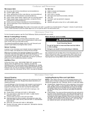
... uses 10% cook power. The cook power and/or temperature (on the vent grille, tilt the grille forward, lift it is not recommended. Dishwasher cleaning is time to soil buildup, keep cavity, microwave inlet cover, cooking rack supports, and area where the door touches the frame clean. Remove two screws on models with convection) for at least 30 minutes after cooking. To reinstall, place the filter into the opening opposite the tab area, swing up , replace vent grille...
... uses 10% cook power. The cook power and/or temperature (on the vent grille, tilt the grille forward, lift it is not recommended. Dishwasher cleaning is time to soil buildup, keep cavity, microwave inlet cover, cooking rack supports, and area where the door touches the frame clean. Remove two screws on models with convection) for at least 30 minutes after cooking. To reinstall, place the filter into the opening opposite the tab area, swing up , replace vent grille...
Owners Manual
Page 5
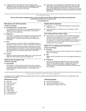
..., replace the fuse or reset the circuit breaker. Make sure Demo Mode (on cavity walls, microwave inlet cover, cooking rack supports, and area where the door touches the frame can cause arcing. Display shows messages ■ A flashing ":" or "PF" means there has been a power failure. Replacement Parts and Cleaning Supplies Following is off . Replace bulb, close door. www.maytag.com Microwave oven will not operate Check the following : ■ Soil buildup Soil buildup on some models), which...
..., replace the fuse or reset the circuit breaker. Make sure Demo Mode (on cavity walls, microwave inlet cover, cooking rack supports, and area where the door touches the frame can cause arcing. Display shows messages ■ A flashing ":" or "PF" means there has been a power failure. Replacement Parts and Cleaning Supplies Following is off . Replace bulb, close door. www.maytag.com Microwave oven will not operate Check the following : ■ Soil buildup Soil buildup on some models), which...

Owners Manual
Page 6
... to Maytag with electrical or plumbing codes, or use your model number and serial number on the label located on the duration of implied warranties of merchantability or fitness, so this warranty. 8. Major appliances with original model/serial numbers that vary from your home of original purchase, when this User Instructions and model number information for factory specified replacement parts and repair labor to correct defects in which it is installed in...
... to Maytag with electrical or plumbing codes, or use your model number and serial number on the label located on the duration of implied warranties of merchantability or fitness, so this warranty. 8. Major appliances with original model/serial numbers that vary from your home of original purchase, when this User Instructions and model number information for factory specified replacement parts and repair labor to correct defects in which it is installed in...
Dimension Guide
Page 1
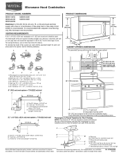
... outlet *30" (76.2 cm) is recommended. diameter round vent C. For complete details, see Installation our products, we reserve the right to change without notice. Specifications subject to round transition piece so that a separate circuit serving only this microwave oven be inside the upper cabinet. Ref. It is recommended that the damper can open freely and fully. 2 ft A (0.6 m) C A. Rectangular to Round Transition...
... outlet *30" (76.2 cm) is recommended. diameter round vent C. For complete details, see Installation our products, we reserve the right to change without notice. Specifications subject to round transition piece so that a separate circuit serving only this microwave oven be inside the upper cabinet. Ref. It is recommended that the damper can open freely and fully. 2 ft A (0.6 m) C A. Rectangular to Round Transition...
Warranty Information
Page 1
..., single-family household use or when it is used in the country in this part that prevent function of the microwave oven opening, behind the door. Any food loss due to repair or replace appliance light bulbs or filters. This major appliance is designed to be provided by a Maytag designated service company. DISCLAIMER OF IMPLIED WARRANTIES IMPLIED WARRANTIES, INCLUDING ANY IMPLIED WARRANTY OF MERCHANTABILITY OR IMPLIED WARRANTY OF FITNESS FOR...
..., single-family household use or when it is used in the country in this part that prevent function of the microwave oven opening, behind the door. Any food loss due to repair or replace appliance light bulbs or filters. This major appliance is designed to be provided by a Maytag designated service company. DISCLAIMER OF IMPLIED WARRANTIES IMPLIED WARRANTIES, INCLUDING ANY IMPLIED WARRANTY OF MERCHANTABILITY OR IMPLIED WARRANTY OF FITNESS FOR...


