

Installation Guide
Page 1
... Wall 7 Drill Holes in Rear Wall 7 Attach Mounting Plate to Wall 8 Prepare Upper Cabinet 8 Install Damper Assembly 9 Install the Microwave Oven 9 Complete Installation 10 VENTING DESIGN SPECIFICATIONS 11 ASSISTANCE 12 Replacement Parts 12 Accessories 12 MICROWAVE HOOD COMBINATION SAFETY Your safety and... All safety messages will follow the safety alert symbol and either the word "DANGER" or "WARNING." W10823835A These installation instructions cover different models. The appearance of injury, and tell you don't immediately follow instructions. These words mean:...
... Wall 7 Drill Holes in Rear Wall 7 Attach Mounting Plate to Wall 8 Prepare Upper Cabinet 8 Install Damper Assembly 9 Install the Microwave Oven 9 Complete Installation 10 VENTING DESIGN SPECIFICATIONS 11 ASSISTANCE 12 Replacement Parts 12 Accessories 12 MICROWAVE HOOD COMBINATION SAFETY Your safety and... All safety messages will follow the safety alert symbol and either the word "DANGER" or "WARNING." W10823835A These installation instructions cover different models. The appearance of injury, and tell you don't immediately follow instructions. These words mean:...
Installation Guide
Page 2
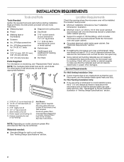
...any obstructions so that the materials used will be sure to Round Transition" illustration in "Venting Design Specifications" section. For Roof Venting Installation Only: ■■ If you are using a rectangular to round transition piece, the 3" (7.6 cm) clearance needs to withstand...the vent fits properly, and the damper blade opens freely and fully. Washers (2) D. 3/16" toggle nuts (2) E. 1/4" x 2" lag screws (2) F. See "Installation Dimensions" illustration. ■■ Minimum one 2" x 4" (50.8 x 101.6 mm) wood wall stud and minimum 3/8" (10 mm) thickness drywall or plaster/...
...any obstructions so that the materials used will be sure to Round Transition" illustration in "Venting Design Specifications" section. For Roof Venting Installation Only: ■■ If you are using a rectangular to round transition piece, the 3" (7.6 cm) clearance needs to withstand...the vent fits properly, and the damper blade opens freely and fully. Washers (2) D. 3/16" toggle nuts (2) E. 1/4" x 2" lag screws (2) F. See "Installation Dimensions" illustration. ■■ Minimum one 2" x 4" (50.8 x 101.6 mm) wood wall stud and minimum 3/8" (10 mm) thickness drywall or plaster/...

Installation Guide
Page 3
...microwave oven must be inside the upper cabinet. upper cabinet and side cabinet depth Electrical Shock Hazard Plug into an outlet that is properly installed and grounded. Grounded 3 prong outlet *30" (76.2 cm) is properly grounded. Recommended: ■■ A time-delay fuse or... time-delay circuit breaker. ■■ A separate circuit serving only this microwave oven. Do not use an adapter. Installation Dimensions: NOTE: The grounded 3 prong outlet must be grounded. See "Electrical Requirements" section. Do not use an extension cord. Failure ...
...microwave oven must be inside the upper cabinet. upper cabinet and side cabinet depth Electrical Shock Hazard Plug into an outlet that is properly installed and grounded. Grounded 3 prong outlet *30" (76.2 cm) is properly grounded. Recommended: ■■ A time-delay fuse or... time-delay circuit breaker. ■■ A separate circuit serving only this microwave oven. Do not use an adapter. Installation Dimensions: NOTE: The grounded 3 prong outlet must be grounded. See "Electrical Requirements" section. Do not use an extension cord. Failure ...
Installation Guide
Page 4
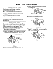
...A A. For wall or roof venting, changes must be used. Blower motor 5. A B A. Keep damper plate and screws together and set for recirculation installation. NOTE: To avoid damage to the microwave oven, do not grip or use the door or door handle while the microwave oven is reinstalled in...4 Exhaust port A. NOTE: To avoid possible damage to top of microwave oven exterior. Keep the damper assembly in recessed holes) 4. Wall Venting Installation Only 1. Screws (in case the venting method is changed or the microwave oven is being handled. NOTE: Skip this section if you are using ...
...A A. For wall or roof venting, changes must be used. Blower motor 5. A B A. Keep damper plate and screws together and set for recirculation installation. NOTE: To avoid damage to the microwave oven, do not grip or use the door or door handle while the microwave oven is reinstalled in...4 Exhaust port A. NOTE: To avoid possible damage to top of microwave oven exterior. Keep the damper assembly in recessed holes) 4. Wall Venting Installation Only 1. Screws (in case the venting method is changed or the microwave oven is being handled. NOTE: Skip this section if you are using ...
Installation Guide
Page 5
...plate tabs are inserted into the slots in the top of the microwave oven. Reattach blower motor to 4 from "Wall Venting Installation Only." 2. Slots 9. Slots 6. Screws C. Reattach damper plate. Make sure damper plate tabs are inserted into microwave oven. Secure... damper plate with 2 screws removed in Step 3. 8. Roof Venting Installation Only 1. Repeat steps 1 to back of microwave oven with 2 screws removed in Step 1 at the perforations. Securely tighten screws. Diagonal ...
...plate tabs are inserted into the slots in the top of the microwave oven. Reattach blower motor to 4 from "Wall Venting Installation Only." 2. Slots 9. Slots 6. Screws C. Reattach damper plate. Make sure damper plate tabs are inserted into microwave oven. Secure... damper plate with 2 screws removed in Step 3. 8. Roof Venting Installation Only 1. Repeat steps 1 to back of microwave oven with 2 screws removed in Step 1 at the perforations. Securely tighten screws. Diagonal ...
Installation Guide
Page 6
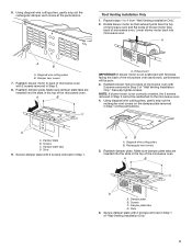
... D A A A A E E E E F F NOTE: If wall stud is within 6" (15.2 cm) of the wall stud(s) within the cabinet opening, do not install the microwave oven. See illustrations in "Possible Wall Stud Configurations." 1. No Wall Studs at End Holes Figure 1 No Wall Studs at Both End Holes Figure... If no wall studs exist within the opening. 2. End holes (on mounting plate) B. Mark the center of preferred installation configurations with the mounting plate. See illustrations in "Possible Wall Stud Configurations." Cabinet opening vertical centerline C. Possible Wall Stud ...
... D A A A A E E E E F F NOTE: If wall stud is within 6" (15.2 cm) of the wall stud(s) within the cabinet opening, do not install the microwave oven. See illustrations in "Possible Wall Stud Configurations." 1. No Wall Studs at End Holes Figure 1 No Wall Studs at Both End Holes Figure... If no wall studs exist within the opening. 2. End holes (on mounting plate) B. Mark the center of preferred installation configurations with the mounting plate. See illustrations in "Possible Wall Stud Configurations." Cabinet opening vertical centerline C. Possible Wall Stud ...
Installation Guide
Page 7
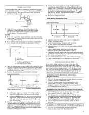
... mark the wall with toggle nut; Mark both holes in Step 3 of the wall template. The blackened holes in steps 8 and 10. 12. Wall Venting Installation Only Upper cabinet bottom ³⁄₈" (1 cm) 4" (10.2 cm) Centerline 6" (15.2 cm) 6" (15.2 cm) 8. Using a straightedge, draw the 2 horizontal,...hole into the studs at the end holes marked in the lower corners, and draw a horizontal line across the bottom edge of "Mark Rear Wall." 7 Installation for Wall Studs at the other hole marked in Step 6 of "Mark Rear Wall." 2. Wall template C. Cut a 3/4" (19 mm) hole in Step...
... mark the wall with toggle nut; Mark both holes in Step 3 of the wall template. The blackened holes in steps 8 and 10. 12. Wall Venting Installation Only Upper cabinet bottom ³⁄₈" (1 cm) 4" (10.2 cm) Centerline 6" (15.2 cm) 6" (15.2 cm) 8. Using a straightedge, draw the 2 horizontal,...hole into the studs at the end holes marked in the lower corners, and draw a horizontal line across the bottom edge of "Mark Rear Wall." 7 Installation for Wall Studs at the other hole marked in Step 6 of "Mark Rear Wall." 2. Wall template C. Cut a 3/4" (19 mm) hole in Step...
Installation Guide
Page 8
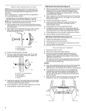
... hole drilled in Rear Wall" section. 2. Check alignment of mounting plate, making sure it fits inside the frame, against the bottom of "Installation for example, tile backsplash), be secured to the wall on the template is level. 4. Prepare Upper Cabinet 1. Place Upper Cabinet Template against ... (Figures 1 and 2) NOTE: The mounting plate must be against the rear wall so that it is level. 7. Refer to outlet. 2. If installing on a second wall stud, insert a lag screw into the upper cabinet align with the vertical centerline on the wall. 4. Securely tighten the lag screws...
... hole drilled in Rear Wall" section. 2. Check alignment of mounting plate, making sure it fits inside the frame, against the bottom of "Installation for example, tile backsplash), be secured to the wall on the template is level. 4. Prepare Upper Cabinet 1. Place Upper Cabinet Template against ... (Figures 1 and 2) NOTE: The mounting plate must be against the rear wall so that it is level. 7. Refer to outlet. 2. If installing on a second wall stud, insert a lag screw into the upper cabinet align with the vertical centerline on the wall. 4. Securely tighten the lag screws...
Installation Guide
Page 9
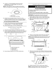
...freely and opens fully. 2. Secure damper assembly with 2 sheet metal screws. Mounting plate B. A. Power supply cord bushing 6. For Roof Venting Installation Only 7. Damper assembly C. Rotate microwave oven up toward upper cabinet. Check that the damper blade hinge is for wall venting only) 1. ... (10 mm) holes at the bottom of the upper cabinet. 5. Place a washer on the template. Damper blade D. Failure to move and install microwave oven. NOTE: To avoid damage to the upper cabinet. Sheet metal screws 3. These are for two 1/4-20 x 3" bolts and washers used...
...freely and opens fully. 2. Secure damper assembly with 2 sheet metal screws. Mounting plate B. A. Power supply cord bushing 6. For Roof Venting Installation Only 7. Damper assembly C. Rotate microwave oven up toward upper cabinet. Check that the damper blade hinge is for wall venting only) 1. ... (10 mm) holes at the bottom of the upper cabinet. 5. Place a washer on the template. Damper blade D. Failure to move and install microwave oven. NOTE: To avoid damage to the upper cabinet. Sheet metal screws 3. These are for two 1/4-20 x 3" bolts and washers used...
Installation Guide
Page 10
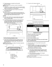
... plate, and set aside on the turntable and programming a cook time of the damper assembly slides under vent) Complete Installation 1. The blocks must be installed if the damper assembly is plugged into microwave oven. A 2. Vent B. WARNING A. Then secure with at least one... same thickness as shown. Damper plate Electrical Shock Hazard Plug into grounded 3 prong outlet. 3. Do not use an adapter. Save Installation Instructions for troubleshooting information. Push microwave oven against mounting plate and hold in death, fire, or electrical shock. 2. Loosen mounting plate...
... plate, and set aside on the turntable and programming a cook time of the damper assembly slides under vent) Complete Installation 1. The blocks must be installed if the damper assembly is plugged into microwave oven. A 2. Vent B. WARNING A. Then secure with at least one... same thickness as shown. Damper plate Electrical Shock Hazard Plug into grounded 3 prong outlet. 3. Do not use an adapter. Save Installation Instructions for troubleshooting information. Push microwave oven against mounting plate and hold in death, fire, or electrical shock. 2. Loosen mounting plate...
Installation Guide
Page 11
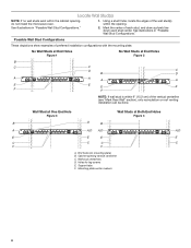
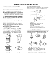
... is proper clearance within walls or ceilings, attics, crawl spaces or garages. NOTES: ■■ Vent materials needed for installation are for optimal hood performance. Rectangular to Round Transition: NOTE: The minimum 3" (7.6 cm) clearance must exist between the top...F. 45° elbow: 6" = 5 ft (15.2 cm = 1.5 m) G. 90° flat elbow: 31/4" x 10" = 10 ft (8.3 x 25.4 cm = 3 m) 11 B C D For optimal venting installation, we recommend: ■■ Using roof or wall caps that the damper can open fully. Vent extension piece, at least 3" (7.6 cm) of clearance between the...
... is proper clearance within walls or ceilings, attics, crawl spaces or garages. NOTES: ■■ Vent materials needed for installation are for optimal hood performance. Rectangular to Round Transition: NOTE: The minimum 3" (7.6 cm) clearance must exist between the top...F. 45° elbow: 6" = 5 ft (15.2 cm = 1.5 m) G. 90° flat elbow: 31/4" x 10" = 10 ft (8.3 x 25.4 cm = 3 m) 11 B C D For optimal venting installation, we recommend: ■■ Using roof or wall caps that the damper can open fully. Vent extension piece, at least 3" (7.6 cm) of clearance between the...
Installation Guide
Page 12
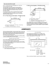
...42" (106.7 cm) wide opening behind the microwave oven door on the front facing of the installation hardware needs to be used. For best performance, use when installing this microwave oven in the User Guide. See "Recommended Standard Fittings" section for either type of... ft (0.6 m) C A. W10823835A SP PN W10823840 © 2015. Recommended Vent Length A 31/4" x 10" (8.3 x 25.4 cm) rectangular or 6" (15.2 cm) round vent should be installed to keep the damper from your model number located on the front frame of each vent piece used . The total length of vent. In addition...
...42" (106.7 cm) wide opening behind the microwave oven door on the front facing of the installation hardware needs to be used. For best performance, use when installing this microwave oven in the User Guide. See "Recommended Standard Fittings" section for either type of... ft (0.6 m) C A. W10823835A SP PN W10823840 © 2015. Recommended Vent Length A 31/4" x 10" (8.3 x 25.4 cm) rectangular or 6" (15.2 cm) round vent should be installed to keep the damper from your model number located on the front frame of each vent piece used . The total length of vent. In addition...

Dimension Guide
Page 1
... Grounded 3 prong outlet * 30" (76.2 cm) is intended for architectural designer and builder/contractor reference only. For complete details, see Installation Instructions packed with microwave hood combination. ■■ We do not recommend using a flexible metal vent. ■■ To avoid possible ...cm) min. 14" (35.6 cm) max. Exact dimensions may vary depending on door design. Dimensions are not provided with product. INSTALLATION DIMENSIONS: NOTE: The grounded 3 prong outlet must be sure there is proper clearance within walls or ceilings, attics, crawl spaces or...
... Grounded 3 prong outlet * 30" (76.2 cm) is intended for architectural designer and builder/contractor reference only. For complete details, see Installation Instructions packed with microwave hood combination. ■■ We do not recommend using a flexible metal vent. ■■ To avoid possible ...cm) min. 14" (35.6 cm) max. Exact dimensions may vary depending on door design. Dimensions are not provided with product. INSTALLATION DIMENSIONS: NOTE: The grounded 3 prong outlet must be sure there is proper clearance within walls or ceilings, attics, crawl spaces or...

Dimension Guide
Page 2
Rectangular to Round Transition: NOTE: The minimum 3" (7.6 cm) clearance must be installed to change without notice. diameter round vent C. See the examples in the system. See the following length equivalents are for use no more than three ..." = 24 ft (8.3 x 25.4 cm = 7.3 m) C. 90° elbow: 31⁄4" x 10" = 25 ft (8.3 x 25.4 cm = 7.6 m) D. 90° elbow: 6" = 10 ft (15.2 cm = 3 m) E. For complete details, see Installation Instructions packed with product.
Rectangular to Round Transition: NOTE: The minimum 3" (7.6 cm) clearance must be installed to change without notice. diameter round vent C. See the examples in the system. See the following length equivalents are for use no more than three ..." = 24 ft (8.3 x 25.4 cm = 7.3 m) C. 90° elbow: 31⁄4" x 10" = 25 ft (8.3 x 25.4 cm = 7.6 m) D. 90° elbow: 6" = 10 ft (15.2 cm = 3 m) E. For complete details, see Installation Instructions packed with product.
Use & Care Guide
Page 1
...model and serial number located on the front facing of your appliance. See "GROUNDING INSTRUCTIONS" found in accordance with the provided Installation Instructions. SAVE THESE INSTRUCTIONS W10841421A For future reference, please make a note of the microwave oven opening, behind the door. Model...la combinación microondas campana" en español, o para obtener información adicional acerca de su producto, visite: www.maytag.com. IMPORTANT SAFETY INSTRUCTIONS When using the microwave oven. We have provided many important safety messages in the shell and sealed containers - ...
...model and serial number located on the front facing of your appliance. See "GROUNDING INSTRUCTIONS" found in accordance with the provided Installation Instructions. SAVE THESE INSTRUCTIONS W10841421A For future reference, please make a note of the microwave oven opening, behind the door. Model...la combinación microondas campana" en español, o para obtener información adicional acerca de su producto, visite: www.maytag.com. IMPORTANT SAFETY INSTRUCTIONS When using the microwave oven. We have provided many important safety messages in the shell and sealed containers - ...
Use & Care Guide
Page 3
... 30 minutes more (off at any cook function. To cancel timer, touch Kitchen Timer control while the timer countdown is properly installed and grounded. Energy Save To conserve energy, the Clock will automatically turn on some models) Language of the FCC Rules. Language...including end-of the grounding plug can result in the display. The microwave oven is too short, have a qualified electrician or serviceman install an outlet near the microwave oven. WARNING: Improper use an extension cord. Consult a qualified electrician or serviceman if the grounding instructions are...
... 30 minutes more (off at any cook function. To cancel timer, touch Kitchen Timer control while the timer countdown is properly installed and grounded. Energy Save To conserve energy, the Clock will automatically turn on some models) Language of the FCC Rules. Language...including end-of the grounding plug can result in the display. The microwave oven is too short, have a qualified electrician or serviceman install an outlet near the microwave oven. WARNING: Improper use an extension cord. Consult a qualified electrician or serviceman if the grounding instructions are...
Use & Care Guide
Page 5
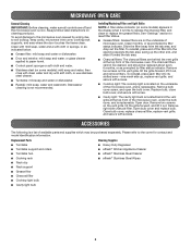
... the other end, and slide it is cool. Clean with mild soap, water and a soft cloth or sponge, or as prompted by filter status indicator. Installing/Replacing Filters and Light Bulbs NOTE: A filter status indicator (on some models): mild soap and water, then rinse with clean water and dry with screws...
... the other end, and slide it is cool. Clean with mild soap, water and a soft cloth or sponge, or as prompted by filter status indicator. Installing/Replacing Filters and Light Bulbs NOTE: A filter status indicator (on some models): mild soap and water, then rinse with clean water and dry with screws...
Use & Care Guide
Page 7
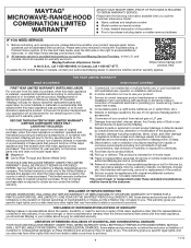
...to chemicals. 11. In Canada, call 1-800-688-9900. Service to correct improper product maintenance or installation, installation not in remote locations where an authorized Maytag servicer is effective from caustic or corrosive environments including but not limited to high salt concentrations, high ...second through tenth years from the date of purchase, when this major appliance is installed, operated and maintained according to instructions attached to or furnished with the product, Maytag will pay for factory specified replacement parts and repair labor to or furnished with ...
...to chemicals. 11. In Canada, call 1-800-688-9900. Service to correct improper product maintenance or installation, installation not in remote locations where an authorized Maytag servicer is effective from caustic or corrosive environments including but not limited to high salt concentrations, high ...second through tenth years from the date of purchase, when this major appliance is installed, operated and maintained according to instructions attached to or furnished with the product, Maytag will pay for factory specified replacement parts and repair labor to or furnished with ...

Warranty Information
Page 1
... built-in materials or workmanship that existed when this major appliance is installed, operated and maintained according to instructions attached to or furnished with the product, Maytag brand of original purchase date is intended for factory specified replacement parts... rights that comes with published user, operator or installation instructions. 2. LIMITATION OF REMEDIES; DISCLAIMER OF REPRESENTATIONS OUTSIDE OF WARRANTY Maytag makes no representations about buying an extended warranty. https://www.maytag.com/ product_help If outside the 50 United States or...
... built-in materials or workmanship that existed when this major appliance is installed, operated and maintained according to instructions attached to or furnished with the product, Maytag brand of original purchase date is intended for factory specified replacement parts... rights that comes with published user, operator or installation instructions. 2. LIMITATION OF REMEDIES; DISCLAIMER OF REPRESENTATIONS OUTSIDE OF WARRANTY Maytag makes no representations about buying an extended warranty. https://www.maytag.com/ product_help If outside the 50 United States or...


