Installation Instructions
Page 1
... 10 Complete Installation 11 VENTING DESIGN SPECIFICATIONS 12 ASSISTANCE 14 Replacement Parts 14 Accessories 14 MICROWAVE HOOD COMBINATION SAFETY W11485889B The appearance of Contents MICROWAVE HOOD COMBINATION SAFETY 1 INSTALLATION REQUIREMENTS 2 Tools and Parts 2 Remove Cardboard Template 2 Location Requirements 2 Product Dimensions...slightly from the illustration in Rear Wall 8 Attach Mounting Plate to and including 36" (91.4 cm) wide. MICROWAVE HOOD COMBINATION INSTALLATION INSTRUCTIONS This product is suitable for use above electric or gas cooking products up to Wall 8 ...
... 10 Complete Installation 11 VENTING DESIGN SPECIFICATIONS 12 ASSISTANCE 14 Replacement Parts 14 Accessories 14 MICROWAVE HOOD COMBINATION SAFETY W11485889B The appearance of Contents MICROWAVE HOOD COMBINATION SAFETY 1 INSTALLATION REQUIREMENTS 2 Tools and Parts 2 Remove Cardboard Template 2 Location Requirements 2 Product Dimensions...slightly from the illustration in Rear Wall 8 Attach Mounting Plate to and including 36" (91.4 cm) wide. MICROWAVE HOOD COMBINATION INSTALLATION INSTRUCTIONS This product is suitable for use above electric or gas cooking products up to Wall 8 ...
Installation Instructions
Page 2
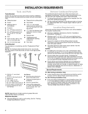
...one 2" x 4" (5.1 x 10.2 cm) wood wall stud and minimum 3/8" (1 cm) thickness drywall or plaster/lath within cabinet opening where the microwave oven will not discolor, delaminate, or sustain other types of the cardboard packaging. 2. See the "Venting Design Specifications" section. 2 Washers (2) D.... Shown: bolts (2) B. 1/4-20 x 3" flat-head bolts (2) ■ Mounting plate (attached to withstand the heat produced by the microwave oven for wood studs. See "User Instructions.") Remove Cardboard Template The cardboard piece from the rest of wall structures, be included. Set ...
...one 2" x 4" (5.1 x 10.2 cm) wood wall stud and minimum 3/8" (1 cm) thickness drywall or plaster/lath within cabinet opening where the microwave oven will not discolor, delaminate, or sustain other types of the cardboard packaging. 2. See the "Venting Design Specifications" section. 2 Washers (2) D.... Shown: bolts (2) B. 1/4-20 x 3" flat-head bolts (2) ■ Mounting plate (attached to withstand the heat produced by the microwave oven for wood studs. See "User Instructions.") Remove Cardboard Template The cardboard piece from the rest of wall structures, be included. Set ...
Installation Instructions
Page 3
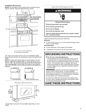
...cabinet depth Electrical Shock Hazard Plug into an outlet that is too short, have a qualified electrician or serviceman install an outlet near the microwave oven. The bump out mounting kit (part # W11185746) is equipped with a cord having a grounding wire with a fuse or circuit... breaker Recommended: ■ A time-delay fuse or time-delay circuit breaker ■ A separate circuit serving only this microwave oven GROUNDING INSTRUCTIONS For all governing codes and ordinances. Grounded 3 prong outlet *30" (76.2 cm) is properly grounded. Exact dimensions may ...
...cabinet depth Electrical Shock Hazard Plug into an outlet that is too short, have a qualified electrician or serviceman install an outlet near the microwave oven. The bump out mounting kit (part # W11185746) is equipped with a cord having a grounding wire with a fuse or circuit... breaker Recommended: ■ A time-delay fuse or time-delay circuit breaker ■ A separate circuit serving only this microwave oven GROUNDING INSTRUCTIONS For all governing codes and ordinances. Grounded 3 prong outlet *30" (76.2 cm) is properly grounded. Exact dimensions may ...

Installation Instructions
Page 4
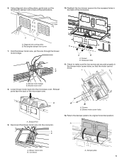
..., remove it and set it may be used. Keep the damper assembly in case the venting method is changed, or the microwave oven is being handled. A A. A A. Blower motor wire B. Damper plate A. Blower screws (in recessed holes) 4. Connector 5. A A. NOTE: To avoid... if you are using recirculation installation. A B A. Blower Motor 4 NOTE: To avoid damage to back of microwave oven, and set for recirculation installation. Screws 2. Rotate Blower Motor The microwave oven is being handled. 3. For wall or roof venting, changes must be made to the work surface, cover...
..., remove it and set it may be used. Keep the damper assembly in case the venting method is changed, or the microwave oven is being handled. A A. A A. Blower motor wire B. Damper plate A. Blower screws (in recessed holes) 4. Connector 5. A A. NOTE: To avoid... if you are using recirculation installation. A B A. Blower Motor 4 NOTE: To avoid damage to back of microwave oven, and set for recirculation installation. Screws 2. Rotate Blower Motor The microwave oven is being handled. 3. For wall or roof venting, changes must be made to the work surface, cover...
Installation Instructions
Page 5
...Blower motor wire 8. A A. Exhaust Port 9. A A. Damper plate 5 A. Return the damper plate to make sure the two screws are secured properly in the back of the microwave oven. 6. Blower motor wire B. Blower motor bridge B. A B A B A. Screws B. Reattach the two blower screws into the recessed holes in the blower motor screw holes, .... 10. Diagonal wire cutting pliers B. Rectangular damper vent cover 7. A B A B A. Check to its original horizontal position. Exhaust ports face the back of the microwave. Reconnect the blower motor wire into the...
...Blower motor wire 8. A A. Exhaust Port 9. A A. Damper plate 5 A. Return the damper plate to make sure the two screws are secured properly in the back of the microwave oven. 6. Blower motor wire B. Blower motor bridge B. A B A B A. Screws B. Reattach the two blower screws into the recessed holes in the blower motor screw holes, .... 10. Diagonal wire cutting pliers B. Rectangular damper vent cover 7. A B A B A. Check to its original horizontal position. Exhaust ports face the back of the microwave. Reconnect the blower motor wire into the...
Installation Instructions
Page 6
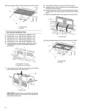
... diagonal wire cutting pliers, gently snip out the rectangular vent covers on the damper plate at the perforations. Reconnect the blower motor wire into microwave oven. A B A. Diagonal wire cutting pliers 7. Damper plate B. Repeat Step 2 from "Wall Venting Installation Only." 4. Check to its... original horizontal position. Exhaust port IMPORTANT: If blower motor is not positioned with two screws removed in the back of microwave oven. Repeat Step 4 from "Wall Venting Installation Only." 2. Damper plate 12. Lower blower motor back into the connector. 9....
... diagonal wire cutting pliers, gently snip out the rectangular vent covers on the damper plate at the perforations. Reconnect the blower motor wire into microwave oven. A B A. Diagonal wire cutting pliers 7. Damper plate B. Repeat Step 2 from "Wall Venting Installation Only." 4. Check to its... original horizontal position. Exhaust port IMPORTANT: If blower motor is not positioned with two screws removed in the back of microwave oven. Repeat Step 4 from "Wall Venting Installation Only." 2. Damper plate 12. Lower blower motor back into the connector. 9....

Installation Instructions
Page 7
...Wall Studs at End Holes Figure 4 B D B A A,D A,D A,D E E E E C C C C F F A. Mounting plate center markers Mark Rear Wall The microwave oven must align with the mounting plate. A A. Locate Wall Stud(s) NOTE: If no wall studs exist within the opening. Using a stud finder, locate the edges... of the opening. See illustrations in "Possible Wall Stud Configurations." Cabinet opening , do not install the microwave oven. 1. See illustrations in "Possible Wall Stud Configurations." 2. End holes (on a minimum of one lag screw, preferably...
...Wall Studs at End Holes Figure 4 B D B A A,D A,D A,D E E E E C C C C F F A. Mounting plate center markers Mark Rear Wall The microwave oven must align with the mounting plate. A A. Locate Wall Stud(s) NOTE: If no wall studs exist within the opening. Using a stud finder, locate the edges... of the opening. See illustrations in "Possible Wall Stud Configurations." Cabinet opening , do not install the microwave oven. 1. See illustrations in "Possible Wall Stud Configurations." 2. End holes (on a minimum of one lag screw, preferably...

Installation Instructions
Page 9
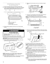
...3/16-24 x 3" round-head bolt B. Check alignment of mounting plate, making sure it is for two 1/4-20 x 3" bolts and washers used to secure the microwave oven to make sure toggle nut has opened against drywall. Start a toggle nut on the wall. 2. Wall Studs at One End Hole (Figure 3) 1. Position mounting... the drywall, and finger tighten the bolts to the upper cabinet. Remove all lag screws and bolts. NOTE: ■ If the wall behind the microwave oven (as shown. Cut 3/4" (1.9 cm) hole at one corner of the tiles rather than the drywall). 4. Make sure the 10" (25.4...
...3/16-24 x 3" round-head bolt B. Check alignment of mounting plate, making sure it is for two 1/4-20 x 3" bolts and washers used to secure the microwave oven to make sure toggle nut has opened against drywall. Start a toggle nut on the wall. 2. Wall Studs at One End Hole (Figure 3) 1. Position mounting... the drywall, and finger tighten the bolts to the upper cabinet. Remove all lag screws and bolts. NOTE: ■ If the wall behind the microwave oven (as shown. Cut 3/4" (1.9 cm) hole at one corner of the tiles rather than the drywall). 4. Make sure the 10" (25.4...
Installation Instructions
Page 10
... plate. Loosen mounting plate screws. Repeat steps 3 through the wall, make sure the damper assembly fits easily into microwave oven. Tighten bolts until there is closed and taped shut. 4. NOTES: ■ Some upper cabinets may not have packing spaces,... install your microwave oven start from Step 2. 2. A. Handle the microwave oven gently. 1. NOTE: If venting through 6. 11. Rotate microwave oven up toward upper cabinet. Position the damper assembly on a covered surface. 9. Longer or...
... plate. Loosen mounting plate screws. Repeat steps 3 through the wall, make sure the damper assembly fits easily into microwave oven. Tighten bolts until there is closed and taped shut. 4. NOTES: ■ Some upper cabinets may not have packing spaces,... install your microwave oven start from Step 2. 2. A. Handle the microwave oven gently. 1. NOTE: If venting through 6. 11. Rotate microwave oven up toward upper cabinet. Position the damper assembly on a covered surface. 9. Longer or...
Installation Instructions
Page 11
...blocks must be the same thickness as shown. A. WARNING A 15-20 mm B A. Do not use an adapter. If the microwave oven does not operate: ■ Check that a household fuse has not blown, or that the long tab of the damper assembly... plugged into grounded 3 prong outlet. 3. Bolts NOTE: Avoid damage to damper assembly. Then secure with tools. A B C D E F A. Raised tabs B. Plug microwave oven into a grounded 3 prong outlet. ■ See the User Instructions for troubleshooting information. The installation is not positioned as the space between the upper cabinet...
...blocks must be the same thickness as shown. A. WARNING A 15-20 mm B A. Do not use an adapter. If the microwave oven does not operate: ■ Check that a household fuse has not blown, or that the long tab of the damper assembly... plugged into grounded 3 prong outlet. 3. Bolts NOTE: Avoid damage to damper assembly. Then secure with tools. A B C D E F A. Raised tabs B. Plug microwave oven into a grounded 3 prong outlet. ■ See the User Instructions for troubleshooting information. The installation is not positioned as the space between the upper cabinet...
Installation Instructions
Page 12
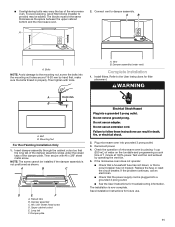
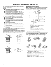
...installing two elbows together, for use when figuring vent length. Rectangular-to -round transition is used, be sure there are not provided with microwave hood combination. ■ We do not recommend using recirculation installation. If venting through the roof, and rectangular-to -Round Transition NOTE: ...B. 6" (15.2 cm) minimum diameter round vent C. Vent extension piece, at least 3" (7.6 cm) of clearance between the top of the microwave oven and the rectangular-to-round transition piece so that have backdraft dampers. ■ Using a rigid metal vent. ■ Using the most ...
...installing two elbows together, for use when figuring vent length. Rectangular-to -round transition is used, be sure there are not provided with microwave hood combination. ■ We do not recommend using recirculation installation. If venting through the roof, and rectangular-to -Round Transition NOTE: ...B. 6" (15.2 cm) minimum diameter round vent C. Vent extension piece, at least 3" (7.6 cm) of clearance between the top of the microwave oven and the rectangular-to-round transition piece so that have backdraft dampers. ■ Using a rigid metal vent. ■ Using the most ...
Installation Instructions
Page 14
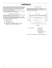
... numbers located on the front frame of the installation hardware needs to use when installing this microwave oven in the "Tools and Parts" section) A A. Each panel is located behind the microwave oven door on the front facing of available replacement parts. Following is a list of the... dealer to be found on the model and serial number plate, which is 3" (7.6 cm) wide. Replacement Parts If any of the microwave oven. Filler panels Filler Panel Kits: 8171336 White 8171337 Black 8171338 Biscuit 8171339 Stainless Steel 99403 Almond See your authorized dealer or service center...
... numbers located on the front frame of the installation hardware needs to use when installing this microwave oven in the "Tools and Parts" section) A A. Each panel is located behind the microwave oven door on the front facing of available replacement parts. Following is a list of the... dealer to be found on the model and serial number plate, which is 3" (7.6 cm) wide. Replacement Parts If any of the microwave oven. Filler panels Filler Panel Kits: 8171336 White 8171337 Black 8171338 Biscuit 8171339 Stainless Steel 99403 Almond See your authorized dealer or service center...

