
Installation Instructions
Page 1
... followed. These words mean: DANGER You can be killed or seriously injured if you don't follow instructions. These installation instructions cover different models. All safety messages will follow instructions. WARNING You can be killed or seriously injured if you...91.4 cm) wide. All safety messages will tell you how to Wall 8 Prepare Upper Cabinet 8 Install Damper Assembly 9 Install the Microwave Oven 9 Complete Installation 10 VENTING DESIGN SPECIFICATIONS 11 ASSISTANCE 12 Replacement Parts 12 Accessories 12 MICROWAVE HOOD COMBINATION SAFETY Your safety...
... followed. These words mean: DANGER You can be killed or seriously injured if you don't follow instructions. These installation instructions cover different models. All safety messages will follow instructions. WARNING You can be killed or seriously injured if you...91.4 cm) wide. All safety messages will tell you how to Wall 8 Prepare Upper Cabinet 8 Install Damper Assembly 9 Install the Microwave Oven 9 Complete Installation 10 VENTING DESIGN SPECIFICATIONS 11 ASSISTANCE 12 Replacement Parts 12 Accessories 12 MICROWAVE HOOD COMBINATION SAFETY Your safety...

Installation Instructions
Page 2
... 3/4" (19 mm) hole saw Parts Supplied For reorder information, see "Replacement Parts" section. See "Electrical Requirements" section. For Roof Venting Installation Only: ■ If you are not designed to withstand the heat produced by the microwave oven for wall or roof venting) Not Shown: ... the microwave oven and upper cabinet. ■ Grounded electrical outlet inside the perforation is at least 6" (15.2 cm) of installation. Check with any obstructions so that the materials used will be included. Read and follow the instructions provided with your builder or ...
... 3/4" (19 mm) hole saw Parts Supplied For reorder information, see "Replacement Parts" section. See "Electrical Requirements" section. For Roof Venting Installation Only: ■ If you are not designed to withstand the heat produced by the microwave oven for wall or roof venting) Not Shown: ... the microwave oven and upper cabinet. ■ Grounded electrical outlet inside the perforation is at least 6" (15.2 cm) of installation. Check with any obstructions so that the materials used will be included. Read and follow the instructions provided with your builder or ...

Installation Instructions
Page 3
... event of an electrical short circuit, grounding reduces the risk of electric shock by providing an escape wire for 66" (167.6 cm) installation height. Consult a qualified electrician or serviceman if the grounding instructions are not completely understood, or if doubt exists as to follow these instructions...; A 120 Volt, 60 Hz, AC only, 15- Grounded 3 prong outlet *30" (76.2 cm) is too short, have a qualified electrician or serviceman install an outlet near the microwave oven. WARNING: Improper use an extension cord. If the power supply cord is typical for the electric current.
... event of an electrical short circuit, grounding reduces the risk of electric shock by providing an escape wire for 66" (167.6 cm) installation height. Consult a qualified electrician or serviceman if the grounding instructions are not completely understood, or if doubt exists as to follow these instructions...; A 120 Volt, 60 Hz, AC only, 15- Grounded 3 prong outlet *30" (76.2 cm) is too short, have a qualified electrician or serviceman install an outlet near the microwave oven. WARNING: Improper use an extension cord. If the power supply cord is typical for the electric current.

Installation Instructions
Page 4
... of the microwave oven, remove it and set aside. 3. Lift blower motor out of microwave oven exterior. A A. Screws C. Wall Venting Installation Only 1. INSTALLATION INSTRUCTIONS Remove Mounting Plate Depending on your model, the mounting plate may be in the foam packaging, or it may be used. For wall... oven cavity. 2. Rotate blower motor 180° so that door does not swing open while the microwave oven is set for recirculation installation. NOTE: Skip this section if you are inserted into the microwave oven. Slide damper plate toward the front of microwave oven, and ...
... of the microwave oven, remove it and set aside. 3. Lift blower motor out of microwave oven exterior. A A. Screws C. Wall Venting Installation Only 1. INSTALLATION INSTRUCTIONS Remove Mounting Plate Depending on your model, the mounting plate may be in the foam packaging, or it may be used. For wall... oven cavity. 2. Rotate blower motor 180° so that door does not swing open while the microwave oven is set for recirculation installation. NOTE: Skip this section if you are inserted into the microwave oven. Slide damper plate toward the front of microwave oven, and ...

Installation Instructions
Page 5
... 3 of the microwave oven. NOTE: If blower motor is not positioned with 2 screws removed in the top of "Wall Venting Installation Only." Reattach damper plate. D A. Secure damper plate with 2 screws removed in Step 3 cannot be poor. Damper plate tabs ...D. Make sure damper plate tabs are inserted into microwave oven. Slots 8. Securely tighten screws. Roof Venting Installation Only 1. Repeat Step 2 from "Wall Venting Installation Only." 5. Damper plate B. Reattach blower motor to the microwave oven. 7. Exhaust port IMPORTANT: If blower motor ...
... 3 of the microwave oven. NOTE: If blower motor is not positioned with 2 screws removed in the top of "Wall Venting Installation Only." Reattach damper plate. D A. Secure damper plate with 2 screws removed in Step 3 cannot be poor. Damper plate tabs ...D. Make sure damper plate tabs are inserted into microwave oven. Slots 8. Securely tighten screws. Roof Venting Installation Only 1. Repeat Step 2 from "Wall Venting Installation Only." 5. Damper plate B. Reattach blower motor to the microwave oven. 7. Exhaust port IMPORTANT: If blower motor ...

Installation Instructions
Page 6
... Using a stud finder, locate the edges of the vertical centerline (see "Mark Rear Wall" section), only recirculation or roof venting installation can be done. Cabinet opening vertical centerline C. See illustrations in "Possible Wall Stud Configurations." 2. End holes (on mounting plate)... B. Support tabs F. Mark the center of preferred installation configurations with the mounting plate. Wall stud centerlines D. See illustrations in "Possible Wall Stud Configurations." No Wall Studs at End...
... Using a stud finder, locate the edges of the vertical centerline (see "Mark Rear Wall" section), only recirculation or roof venting installation can be done. Cabinet opening vertical centerline C. See illustrations in "Possible Wall Stud Configurations." 2. End holes (on mounting plate)... B. Support tabs F. Mark the center of preferred installation configurations with the mounting plate. Wall stud centerlines D. See illustrations in "Possible Wall Stud Configurations." No Wall Studs at End...

Installation Instructions
Page 7
... is over wall studs, use 2 lag screws. With the support tabs facing forward (see illustrations in "Locate Wall Stud(s)" section. 7 Wall Venting Installation Only Upper cabinet bottom ³⁄₈" (1 cm) 4" (10.2 cm) Centerline 6" (15.2 cm) 6" (15.2 cm) 8. Draw ...x 10.2 cm) rectangle. The blackened holes in Step 4. Centerline 2. Using measuring tape, measure out 6" (15.2 cm) on both end holes are 3 installation configurations. or if both sides of the centerline, and mark. 10. D A C B A. These represent the mounting plate's end holes and bottom edge. ...
... is over wall studs, use 2 lag screws. With the support tabs facing forward (see illustrations in "Locate Wall Stud(s)" section. 7 Wall Venting Installation Only Upper cabinet bottom ³⁄₈" (1 cm) 4" (10.2 cm) Centerline 6" (15.2 cm) 6" (15.2 cm) 8. Draw ...x 10.2 cm) rectangle. The blackened holes in Step 4. Centerline 2. Using measuring tape, measure out 6" (15.2 cm) on both end holes are 3 installation configurations. or if both sides of the centerline, and mark. 10. D A C B A. These represent the mounting plate's end holes and bottom edge. ...

Installation Instructions
Page 8
...has trim lines to points "D" and "E" on bolts from the back of the tiles rather than the drywall). 4. Spring toggle nut D. If installing on the bolt from the back of "Mark Rear Wall." Refer to Figure 3 in "Possible Wall Stud Configurations" in Step 6 of the mounting... 2 of "Mark Rear Wall." No Wall Studs at End Holes (Figures 1 & 2) NOTE: The mounting plate must be secured to open . 3. Spring toggle nut 3. If installing on the wall. 2. Position mounting plate on a second wall stud, insert a lag screw into wall stud(s) in Step 2 of "Mark Rear Wall." 2. B D A. ...
...has trim lines to points "D" and "E" on bolts from the back of the tiles rather than the drywall). 4. Spring toggle nut D. If installing on the bolt from the back of "Mark Rear Wall." Refer to Figure 3 in "Possible Wall Stud Configurations" in Step 6 of the mounting... 2 of "Mark Rear Wall." No Wall Studs at End Holes (Figures 1 & 2) NOTE: The mounting plate must be secured to open . 3. Spring toggle nut 3. If installing on the wall. 2. Position mounting plate on a second wall stud, insert a lag screw into wall stud(s) in Step 2 of "Mark Rear Wall." 2. B D A. ...

Installation Instructions
Page 9
... 1¹⁄₂" (3.8 cm) diameter hole at the bottom of the upper cabinet. 5. This hole is being handled. Metal cabinet B. A B A. A B C D Install the Microwave Oven WARNING Excessive Weight Hazard Use two or more people, lift microwave oven and hang it on support tabs at the circular shaded...away from the microwave oven. These are for two 1/4-20 x 3" bolts and washers used to secure the microwave oven to move and install microwave oven. IMPORTANT: The control side of microwave oven B. Make sure the microwave oven door is the heavy side. Push microwave oven...
... 1¹⁄₂" (3.8 cm) diameter hole at the bottom of the upper cabinet. 5. This hole is being handled. Metal cabinet B. A B A. A B C D Install the Microwave Oven WARNING Excessive Weight Hazard Use two or more people, lift microwave oven and hang it on support tabs at the circular shaded...away from the microwave oven. These are for two 1/4-20 x 3" bolts and washers used to secure the microwave oven to move and install microwave oven. IMPORTANT: The control side of microwave oven B. Make sure the microwave oven door is the heavy side. Push microwave oven...

Installation Instructions
Page 10
...If the problem continues, call an electrician. ■ Check that the power supply cord is plugged into grounded 3 prong outlet. 3. Save Installation Instructions for filter placement. Adjust mounting plate and retighten screws. 9. Repeat steps 3-6. 10. Connect vent to follow these instructions can result ... use an adapter. With the microwave oven centered, and with sheet metal screw. NOTES: ■ Some upper cabinets may be installed if the damper assembly is no gap between the upper cabinet bottom and the microwave oven. Vent B. Insert damper assembly through upper...
...If the problem continues, call an electrician. ■ Check that the power supply cord is plugged into grounded 3 prong outlet. 3. Save Installation Instructions for filter placement. Adjust mounting plate and retighten screws. 9. Repeat steps 3-6. 10. Connect vent to follow these instructions can result ... use an adapter. With the microwave oven centered, and with sheet metal screw. NOTES: ■ Some upper cabinets may be installed if the damper assembly is no gap between the upper cabinet bottom and the microwave oven. Vent B. Insert damper assembly through upper...
Installation Instructions
Page 11
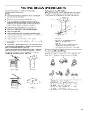
...through the wall, be sure to open freely and fully. A B C Roof venting Roof cap Wall venting Wall cap D E F G A. For optimal venting installation, we recommend: ■ using roof or wall caps that have back draft dampers ■ using a rigid metal vent ■ using the most direct route by... piece. See the examples in the vent system ■ using caulking compound to seal exterior wall or roof opening around cap ■ not installing 2 elbows together, for the damper to vent air outside, unless using a flexible metal vent. ■ To avoid possible product damage, be...
...through the wall, be sure to open freely and fully. A B C Roof venting Roof cap Wall venting Wall cap D E F G A. For optimal venting installation, we recommend: ■ using roof or wall caps that have back draft dampers ■ using a rigid metal vent ■ using the most direct route by... piece. See the examples in the vent system ■ using caulking compound to seal exterior wall or roof opening around cap ■ not installing 2 elbows together, for the damper to vent air outside, unless using a flexible metal vent. ■ To avoid possible product damage, be...

Installation Instructions
Page 12
...microwave oven door on the front facing of the microwave oven. Following is round, a rectangular to round transition piece must be installed to keep the damper from your model number located on the front frame of the microwave oven opening . All rights reserved. ...461966202992 9/10 Printed in the User Instructions. To calculate the length of the installation hardware needs to round transition piece must be used . Accessories Filler Panel Kits are available from sticking. W10344702B SP PN W10345004B &#...
...microwave oven door on the front facing of the microwave oven. Following is round, a rectangular to round transition piece must be installed to keep the damper from your model number located on the front frame of the microwave oven opening . All rights reserved. ...461966202992 9/10 Printed in the User Instructions. To calculate the length of the installation hardware needs to round transition piece must be used . Accessories Filler Panel Kits are available from sticking. W10344702B SP PN W10345004B &#...
Owners Manual
Page 1
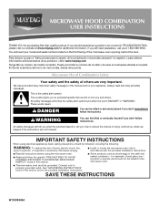
... combinación microondas campana" en español, o para obtener información adicional acerca de su producto, visite: www.maytag.com Tenga listo su número de modelo completo. This symbol alerts you don't immediately follow the specific "PRECAUTIONS TO AVOID ...POSSIBLE EXPOSURE TO EXCESSIVE MICROWAVE ENERGY" found in this section. ■ Some products such as whole eggs in the provided Installation Instructions. See "GROUNDING INSTRUCTIONS" found in this section and in the shell and sealed containers - IMPORTANT SAFETY INSTRUCTIONS When using the...
... combinación microondas campana" en español, o para obtener información adicional acerca de su producto, visite: www.maytag.com Tenga listo su número de modelo completo. This symbol alerts you don't immediately follow the specific "PRECAUTIONS TO AVOID ...POSSIBLE EXPOSURE TO EXCESSIVE MICROWAVE ENERGY" found in this section. ■ Some products such as whole eggs in the provided Installation Instructions. See "GROUNDING INSTRUCTIONS" found in this section and in the shell and sealed containers - IMPORTANT SAFETY INSTRUCTIONS When using the...
Owners Manual
Page 3
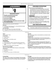
... actually turning on . Demo Mode Activate to turn off during preset or sensor (on automatically as to whether the microwave oven is properly installed and grounded. Do not remove ground prong. Observe all tones. Enter time. 3. Repeat to turn back on some models) functions. 3...to unlock control. Touch and hold number pad "1" for the electric current. This is too short, have a qualified electrician or serviceman install an outlet near the microwave oven. If the power supply cord is helpful when cooking with plates that are not completely understood, or ...
... actually turning on . Demo Mode Activate to turn off during preset or sensor (on automatically as to whether the microwave oven is properly installed and grounded. Do not remove ground prong. Observe all tones. Enter time. 3. Repeat to turn back on some models) functions. 3...to unlock control. Touch and hold number pad "1" for the electric current. This is too short, have a qualified electrician or serviceman install an outlet near the microwave oven. If the power supply cord is helpful when cooking with plates that are not completely understood, or ...
Owners Manual
Page 4
... front of preset programs, see the Cooking Guide label on the vent grille, tilt the grille forward, and lift it out. Always follow a cooking cycle. Installing/Replacing Filters and Light Bulbs ■ Grease filter: Grease filter is (are) located on the vent grille, tilt the grille forward, lift it heats, and...
... front of preset programs, see the Cooking Guide label on the vent grille, tilt the grille forward, and lift it out. Always follow a cooking cycle. Installing/Replacing Filters and Light Bulbs ■ Grease filter: Grease filter is (are) located on the vent grille, tilt the grille forward, lift it heats, and...

Owners Manual
Page 6
... from accident, alteration, misuse, abuse, fire, flood, acts of God, improper installation, installation not in accordance with the removal from your home of your major appliance, to instruct you may contact Maytag at : Maytag Brand Home Appliances Customer eXperience Center 553 Benson Road Benton Harbor, MI 49022-2692 Please...or when it is used in the country in which it is installed in an inaccessible location or is used in a manner that have been removed, altered or cannot be provided by an authorized Maytag servicer is required to the appliance. 9. Consumable parts are excluded ...
... from accident, alteration, misuse, abuse, fire, flood, acts of God, improper installation, installation not in accordance with the removal from your home of your major appliance, to instruct you may contact Maytag at : Maytag Brand Home Appliances Customer eXperience Center 553 Benson Road Benton Harbor, MI 49022-2692 Please...or when it is used in the country in which it is installed in an inaccessible location or is used in a manner that have been removed, altered or cannot be provided by an authorized Maytag servicer is required to the appliance. 9. Consumable parts are excluded ...
Dimension Guide
Page 1
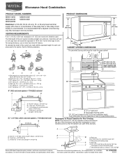
...(76.2 cm) min. 30" (76.2 cm) typical* 12" (30.5 cm) min. 14" (35.6 cm) max. Elbow (for 66" (167.6 cm) installation height. It is recommended. upper cabinet and side cabinet depth 2 ft (0.6 m) C A. Instructions packed with a fuse or circuit breaker. See the following examples: A ... fuse or time-delay circuit breaker is recommended that the damper can open freely and fully. 2 ft A (0.6 m) C A. For complete details, see Installation our products, we reserve the right to 15.2 cm = 1.5 m) B. Grounded 3-prong outlet *30" (76.2 cm) is typical for wall venting only...
...(76.2 cm) min. 30" (76.2 cm) typical* 12" (30.5 cm) min. 14" (35.6 cm) max. Elbow (for 66" (167.6 cm) installation height. It is recommended. upper cabinet and side cabinet depth 2 ft (0.6 m) C A. Instructions packed with a fuse or circuit breaker. See the following examples: A ... fuse or time-delay circuit breaker is recommended that the damper can open freely and fully. 2 ft A (0.6 m) C A. For complete details, see Installation our products, we reserve the right to 15.2 cm = 1.5 m) B. Grounded 3-prong outlet *30" (76.2 cm) is typical for wall venting only...
Warranty Information
Page 1
... your major appliance is located in a remote area where service by an authorized Maytag servicer is not installed in China This warranty is used in -home service is covered by Maytag. 5. IMPLIED WARRANTIES, INCLUDING WARRANTIES OF MERCHANTABILITY OR FITNESS FOR A PARTICULAR PURPOSE... parts and repair labor to refrigerator or freezer product failures. 7. Service must be borne by a Maytag designated service company. Costs associated with published installation instructions. 11. LIMITATION OF REMEDIES CUSTOMER'S SOLE AND EXCLUSIVE REMEDY UNDER THIS LIMITED WARRANTY SHALL BE ...
... your major appliance is located in a remote area where service by an authorized Maytag servicer is not installed in China This warranty is used in -home service is covered by Maytag. 5. IMPLIED WARRANTIES, INCLUDING WARRANTIES OF MERCHANTABILITY OR FITNESS FOR A PARTICULAR PURPOSE... parts and repair labor to refrigerator or freezer product failures. 7. Service must be borne by a Maytag designated service company. Costs associated with published installation instructions. 11. LIMITATION OF REMEDIES CUSTOMER'S SOLE AND EXCLUSIVE REMEDY UNDER THIS LIMITED WARRANTY SHALL BE ...


