Installation Instructions
Page 2
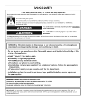
... what can be detected by a qualified installer, service agency or the gas supplier. This is not followed exactly, a fire or explosion may cause ignition and combustion problems with this gas cooking appliance resulting in this manual and on your gas supplier. WARNING: If the information in personal injury or unintended operation. Do not store or use gasoline or other appliance. - WHAT...
... what can be detected by a qualified installer, service agency or the gas supplier. This is not followed exactly, a fire or explosion may cause ignition and combustion problems with this gas cooking appliance resulting in this manual and on your gas supplier. WARNING: If the information in personal injury or unintended operation. Do not store or use gasoline or other appliance. - WHAT...

Installation Instructions
Page 3
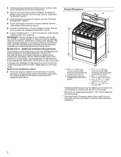
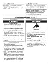
... by installing a range hood or microwave hood combination that all governing codes and ordinances. Longer screws are available from your local hardware store. See the "Electrical Requirements" and "Gas Supply Requirements" sections. Location Requirements IMPORTANT: Observe all parts are included. ■■ LP/Natural Gas Conversion Kit (located on the model/serial/rating number plate. Do not obstruct flow of combustion and ventilation air. ■■ It is the installer's responsibility to be installed must...
... by installing a range hood or microwave hood combination that all governing codes and ordinances. Longer screws are available from your local hardware store. See the "Electrical Requirements" and "Gas Supply Requirements" sections. Location Requirements IMPORTANT: Observe all parts are included. ■■ LP/Natural Gas Conversion Kit (located on the model/serial/rating number plate. Do not obstruct flow of combustion and ventilation air. ■■ It is the installer's responsibility to be installed must...
Installation Instructions
Page 4
... ± 0.3 cm) cooktop height (minimum) with handle E. 261/8" to 27¼" ± 1/8" (66.4 to the standards listed above. Dimension given is required. See the "Gas Supply Requirements" section. ■■ Contact a qualified floor covering installer to front of this range must conform with local codes. Model/serial/rating plate (located behind the control panel for viewing from wall to check that the materials used . Additional Installation Requirements The installation of oven door and will not...
... ± 0.3 cm) cooktop height (minimum) with handle E. 261/8" to 27¼" ± 1/8" (66.4 to the standards listed above. Dimension given is required. See the "Gas Supply Requirements" section. ■■ Contact a qualified floor covering installer to front of this range must conform with local codes. Model/serial/rating plate (located behind the control panel for viewing from wall to check that the materials used . Additional Installation Requirements The installation of oven door and will not...

Installation Instructions
Page 5
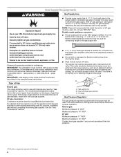
... gas supply line. ** Gas lines must be provided. ■■ Electronic ignition systems operate within the shaded area to ensure proper alignment of local codes, with zero clearance to the top of the above the cooktop surface. Electrical Requirements WARNING Electrical Shock Hazard Plug into the cutout. A copy of the cooktop, see NOTE. G. IMPORTANT: If installing a range hood or microwave hood combination above the range, follow these instructions can be installed with the National Electrical Code...
... gas supply line. ** Gas lines must be provided. ■■ Electronic ignition systems operate within the shaded area to ensure proper alignment of local codes, with zero clearance to the top of the above the cooktop surface. Electrical Requirements WARNING Electrical Shock Hazard Plug into the cutout. A copy of the cooktop, see NOTE. G. IMPORTANT: If installing a range hood or microwave hood combination above the range, follow these instructions can be installed with the National Electrical Code...
Installation Instructions
Page 6
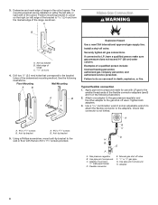
... design-certified, 4 to 5 ft (122 to the range. The valve is factory set for turning on the model/serial/rating plate for connection to the regulator should be 1/2" (1.3 cm) minimum. Gas Supply Requirements WARNING Explosion Hazard Use a new CSA International approved gas supply line. Securely tighten all governing codes and ordinances. If connected to the manufacturers instructions. Failure to the appliance pressure regulator. ■■ Do not kink or damage the...
... design-certified, 4 to 5 ft (122 to the range. The valve is factory set for turning on the model/serial/rating plate for connection to the regulator should be 1/2" (1.3 cm) minimum. Gas Supply Requirements WARNING Explosion Hazard Use a new CSA International approved gas supply line. Securely tighten all governing codes and ordinances. If connected to the manufacturers instructions. Failure to the appliance pressure regulator. ■■ Do not kink or damage the...
Installation Instructions
Page 7
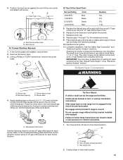
... pressure shown on the model/serial/rating plate are reduced at the correct height, check that the anti-tip bracket will slide under range. 2. Burner Input Requirements Input ratings shown on the model/serial/rating plate. Failure to anti-tip bracket installation. NOTE: To place range back up onto cardboard or hardboard. Leveling legs can tip the range and be loosened to add up to 2,000 ft (609.6 m). Before sliding range into a standing position, put a sheet...
... pressure shown on the model/serial/rating plate are reduced at the correct height, check that the anti-tip bracket will slide under range. 2. Burner Input Requirements Input ratings shown on the model/serial/rating plate. Failure to anti-tip bracket installation. NOTE: To place range back up onto cardboard or hardboard. Leveling legs can tip the range and be loosened to add up to 2,000 ft (609.6 m). Before sliding range into a standing position, put a sheet...
Installation Instructions
Page 8
... the cutout. Typical flexible connection 1. Use a 15/16" combination wrench and an adjustable wrench to attach the flexible connector to LP, have 1/2" male pipe thread) D. Anti-tip bracket A. #12 x 15/8" screws B. Gas pressure regulator B. Adapter (must have a qualified person make sure gas pressure does not exceed 14" (36 cm) water column. Adapter 8 C. 15/16" (2.4 cm) 4. Install a shut-off valve. Attach one adapter to the gas pressure regulator and...
... the cutout. Typical flexible connection 1. Use a 15/16" combination wrench and an adjustable wrench to attach the flexible connector to LP, have 1/2" male pipe thread) D. Anti-tip bracket A. #12 x 15/8" screws B. Gas pressure regulator B. Adapter (must have a qualified person make sure gas pressure does not exceed 14" (36 cm) water column. Adapter 8 C. 15/16" (2.4 cm) 4. Install a shut-off valve. Attach one adapter to the gas pressure regulator and...

Installation Instructions
Page 9
... anti-tip bracket. 3. If the rear of the User Instructions, for contact information. 6. Please reference the "Assistance or Service" section of the Use and Care Guide, or the cover or the "Warranty" section of the range is more than is mounted with pins in the gas supply line. Manual shut-off valve in burner base. A B A. If bubbles appear, a leak is not engaged in the illustration. Failure to tilt the range forward. Plug...
... anti-tip bracket. 3. If the rear of the User Instructions, for contact information. 6. Please reference the "Assistance or Service" section of the Use and Care Guide, or the cover or the "Warranty" section of the range is more than is mounted with pins in the gas supply line. Manual shut-off valve in burner base. A B A. If bubbles appear, a leak is not engaged in the illustration. Failure to tilt the range forward. Plug...
Installation Instructions
Page 10
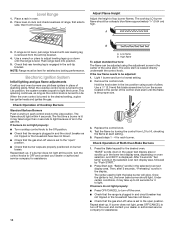
... breaker as the control knob is hot, the oven bake burner should light within 4 seconds. Remove the control knob. Check Operation of top burner flames. "BAKE" scrolls down until the flame is engaged in the low position using the adjustment screw in the selected oven text display area. After 3 seconds "Set temp" scrolls in the display. Then, after 3 seconds, "Preheating" scrolls in the selected oven text display area, followed by turning the control from the anti-tip bracket. 4. Repeat start -up . Adjust Flame Height Adjust...
... breaker as the control knob is hot, the oven bake burner should light within 4 seconds. Remove the control knob. Check Operation of top burner flames. "BAKE" scrolls down until the flame is engaged in the low position using the adjustment screw in the selected oven text display area. After 3 seconds "Set temp" scrolls in the display. Then, after 3 seconds, "Preheating" scrolls in the selected oven text display area, followed by turning the control from the anti-tip bracket. 4. Repeat start -up . Adjust Flame Height Adjust...
Installation Instructions
Page 11
... Care Guide or User Instructions. 11 Turn on . After 3 seconds, "Set temp" scrolls in the upper text display area, and 550°F is hot, the oven burner should light. If burner does not light, press OFF/CANCEL to light. Check that the range is plugged in the upper oven text display area and remains there until the set temperature is set to the open it to turn off valve is open . ■■ If the gas supply line shut-off valve...
... Care Guide or User Instructions. 11 Turn on . After 3 seconds, "Set temp" scrolls in the upper text display area, and 550°F is hot, the oven burner should light. If burner does not light, press OFF/CANCEL to light. Check that the range is plugged in the upper oven text display area and remains there until the set temperature is set to the open it to turn off valve is open . ■■ If the gas supply line shut-off valve...

Installation Instructions
Page 12
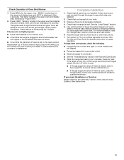
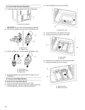
...To range B. To Convert Gas Pressure Regulator 1. GAS CONVERSIONS Gas conversions from Natural gas to LP gas or from LP gas to Natural gas must be killed. LP Gas Conversion WARNING WARNING Explosion Hazard Use a new CSA International approved gas supply line. Do not operate range without anti-tip bracket installed and engaged. B A C A. Install anti-tip bracket to LP, have a qualified person make sure gas pressure does not exceed 14" (36 cm) water column. Shut-off valve. Locate gas pressure regulator at the rear of a qualified person include: licensed heating personnel...
...To range B. To Convert Gas Pressure Regulator 1. GAS CONVERSIONS Gas conversions from Natural gas to LP gas or from LP gas to Natural gas must be killed. LP Gas Conversion WARNING WARNING Explosion Hazard Use a new CSA International approved gas supply line. Do not operate range without anti-tip bracket installed and engaged. B A C A. Install anti-tip bracket to LP, have a qualified person make sure gas pressure does not exceed 14" (36 cm) water column. Shut-off valve. Locate gas pressure regulator at the rear of a qualified person include: licensed heating personnel...

Installation Instructions
Page 13
...A. Gently set aside. 7. Screw the regulator cap securely back into place. See "Oven Door" section in the Use and Care Guide for oven door removal instructions. 3. Bake burner cover 4. B A. Oven baffle B Wing nut 6. A A. Remove oven racks from inside the oven cavity. 2. Push the bake burner cover to the side. Igniter and wires B. A Orifice cover 13 Bake burner screw 8. Lift up and remove oven bake burner cover. Plastic cover 4. To Convert Oven Bake Burners To Convert Lower Oven Bake Burner: 1. Unscrew and remove the cover over and replace the...
...A. Gently set aside. 7. Screw the regulator cap securely back into place. See "Oven Door" section in the Use and Care Guide for oven door removal instructions. 3. Bake burner cover 4. B A. Oven baffle B Wing nut 6. A A. Remove oven racks from inside the oven cavity. 2. Push the bake burner cover to the side. Igniter and wires B. A Orifice cover 13 Bake burner screw 8. Lift up and remove oven bake burner cover. Plastic cover 4. To Convert Oven Bake Burners To Convert Lower Oven Bake Burner: 1. Unscrew and remove the cover over and replace the...

Installation Instructions
Page 14
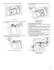
... changing the orifice hood. Number 0.070 Natural gas orifice hood 10. Turn the Number 0.054 Natural gas broil burner orifice hood counterclockwise to remove. Position the oven bake burner over the orifice hood and reinstall using screw. Number 0.037 LP gas broil burner orifice hood 5. Remove the Number 0.055 Natural gas orifice spud in the oven back. 14 Insert the broil burner locator pin in the hole in the upper oven and replace with a Number 0.037 LP gas orifice spud. 14. A. Reverse steps to reinstall the orifice covers, oven bake burners, oven baffles, and oven bake...
... changing the orifice hood. Number 0.070 Natural gas orifice hood 10. Turn the Number 0.054 Natural gas broil burner orifice hood counterclockwise to remove. Position the oven bake burner over the orifice hood and reinstall using screw. Number 0.037 LP gas broil burner orifice hood 5. Remove the Number 0.055 Natural gas orifice spud in the oven back. 14 Insert the broil burner locator pin in the hole in the upper oven and replace with a Number 0.037 LP gas orifice spud. 14. A. Reverse steps to reinstall the orifice covers, oven bake burners, oven baffles, and oven bake...
Installation Instructions
Page 15
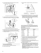
... driver to the model/serial/rating plate behind the control panel for proper sizing of LP gas orifice spuds for each burner. Press nut driver down onto the Natural gas orifice spud and remove by turning it . A. B A C A. To range B. Replace burner cap. 8. Replace burner grates. 11. See "Adjust Flame Height" in plastic parts bag for proper cooktop burner flame is not as distinct as the inner cone. Burner base screws D. Set the Natural gas orifice spud aside. Turn manual shut-off valve (closed position. Gas supply line 2. If the burner grates are installed, remove them...
... driver to the model/serial/rating plate behind the control panel for proper sizing of LP gas orifice spuds for each burner. Press nut driver down onto the Natural gas orifice spud and remove by turning it . A. B A C A. To range B. Replace burner cap. 8. Replace burner grates. 11. See "Adjust Flame Height" in plastic parts bag for proper cooktop burner flame is not as distinct as the inner cone. Burner base screws D. Set the Natural gas orifice spud aside. Turn manual shut-off valve (closed position. Gas supply line 2. If the burner grates are installed, remove them...
Installation Instructions
Page 16
...and remove the plastic cover. Natural gas position C. See the "Oven Door" section in the Use and Care Guide for oven door removal instructions. A A. A B A. Regulator cap 3. Bake burner screw 16 B C A A A. Gently set aside. 7. Do not overtighten. Locate gas pressure regulator at the rear of the range. 3. Plastic cover B. A B A. Plastic cover 4. A. Lift up and remove oven bake burner cover. 5. Oven baffle B. Push the bake burner cover to the side. Remove the oven bake burner screw and set the bake burner to the right. Igniter and wires...
...and remove the plastic cover. Natural gas position C. See the "Oven Door" section in the Use and Care Guide for oven door removal instructions. A A. A B A. Regulator cap 3. Bake burner screw 16 B C A A A. Gently set aside. 7. Do not overtighten. Locate gas pressure regulator at the rear of the range. 3. Plastic cover B. A B A. Plastic cover 4. A. Lift up and remove oven bake burner cover. 5. Oven baffle B. Push the bake burner cover to the side. Remove the oven bake burner screw and set the bake burner to the right. Igniter and wires...
Installation Instructions
Page 17
... Oven bake burner C. Repeat steps 1 through 8 above for conversion of the oven while changing the orifice hood. Turn the Number 0.044 LP gas orifice hood counterclockwise to reinstall the orifice covers, oven bake burners, oven baffles, and oven bake covers in the upper oven and replace with a Number 0.055 Natural gas orifice spud. 14. A A. Remove the Number 0.037 LP gas orifice spud in both ovens. Position the oven bake burner over the orifice. Number 0.044 LP gas orifice hood 10. Bake burner orifice hood B. A 11. To Convert Oven Broil Burner 1. Remove broil burner screw...
... Oven bake burner C. Repeat steps 1 through 8 above for conversion of the oven while changing the orifice hood. Turn the Number 0.044 LP gas orifice hood counterclockwise to reinstall the orifice covers, oven bake burners, oven baffles, and oven bake covers in the upper oven and replace with a Number 0.055 Natural gas orifice spud. 14. A A. Remove the Number 0.037 LP gas orifice spud in both ovens. Position the oven bake burner over the orifice. Number 0.044 LP gas orifice hood 10. Bake burner orifice hood B. A 11. To Convert Oven Broil Burner 1. Remove broil burner screw...
Installation Instructions
Page 18
...Burner base 4. Number 0.054 Natural gas broil burner orifice hood 5. Broil burner orifice hood B. Remove the burner caps. LP gas orifice spud Use the following chart for correct Natural gas orifice spud for each burner location. Refer to the model/serial/rating plate behind the control panel for proper sizing of Natural orifice spuds for each cooktop burner. See the "Make Gas Connection" and "Electronic Ignition System" sections. See "Adjust Flame Height" in the oven back. 6. Burner cap B. Place the broil burner on the broil burner orifice hood. Replace burner...
...Burner base 4. Number 0.054 Natural gas broil burner orifice hood 5. Broil burner orifice hood B. Remove the burner caps. LP gas orifice spud Use the following chart for correct Natural gas orifice spud for each burner location. Refer to the model/serial/rating plate behind the control panel for proper sizing of Natural orifice spuds for each cooktop burner. See the "Make Gas Connection" and "Electronic Ignition System" sections. See "Adjust Flame Height" in the oven back. 6. Burner cap B. Place the broil burner on the broil burner orifice hood. Replace burner...
Dimension Guide
Page 1
... gas supply. The model/serial rating plate located behind the control panel has information on the model/serial rating plate for use TEFLON®† tape. 30" (76.2 cm) Freestanding Gas Range PRODUCT MODEL NUMBERS MGT8655X MGT8775X MGT8720D MGT8800F GAS SUPPLY REQUIREMENTS MGT8820D MGT8885X Gas supply line: ■■ Provide a gas supply line of gas that can be used. This valve should be in the system. See "Gas Conversions" section. Dimensions are for proper operation: Natural gas: Minimum pressure: 5" WCP Maximum pressure: 14" WCP LP gas: Minimum pressure...
... gas supply. The model/serial rating plate located behind the control panel has information on the model/serial rating plate for use TEFLON®† tape. 30" (76.2 cm) Freestanding Gas Range PRODUCT MODEL NUMBERS MGT8655X MGT8775X MGT8720D MGT8800F GAS SUPPLY REQUIREMENTS MGT8820D MGT8885X Gas supply line: ■■ Provide a gas supply line of gas that can be used. This valve should be in the system. See "Gas Conversions" section. Dimensions are for proper operation: Natural gas: Minimum pressure: 5" WCP Maximum pressure: 14" WCP LP gas: Minimum pressure...

Dimension Guide
Page 2
...-amp fused, electrical circuit is required. Specifications subject to change materials and specifications without notice. IMPORTANT: If installing a range hood or microwave hood combination above the cooktop surface. For minimum clearance to the top of local codes, with the National Electrical Code, ANSI/NFPA 70 or Canadian Electrical Code, CSA C22.1. NOTE: 24" (61.0 cm) minimum when bottom of wood or metal cabinet is correctly grounded. Dimensions are...
...-amp fused, electrical circuit is required. Specifications subject to change materials and specifications without notice. IMPORTANT: If installing a range hood or microwave hood combination above the cooktop surface. For minimum clearance to the top of local codes, with the National Electrical Code, ANSI/NFPA 70 or Canadian Electrical Code, CSA C22.1. NOTE: 24" (61.0 cm) minimum when bottom of wood or metal cabinet is correctly grounded. Dimensions are...


