Installation Instructions
Page 1
Installer: Leave installation instructions with the homeowner. W10196161E INSTALLATION INSTRUCTIONS 30" (76.2 CM) FREESTANDING GAS RANGES Table of Contents RANGE SAFETY...2 INSTALLATION REQUIREMENTS 4 Tools and Parts...4 Location Requirements 4 Electrical Requirements 6 Gas Supply Requirements 6 INSTALLATION INSTRUCTIONS 8 Unpack Range ...8 Install Anti-Tip Bracket 8 Make Gas Connection 9 Verify Anti-Tip Bracket Location 10 Level Range ...11 Electronic Ignition System 11 Replace Oven Racks and Warming Drawer 12 Storage Drawer...13 Complete...
Installer: Leave installation instructions with the homeowner. W10196161E INSTALLATION INSTRUCTIONS 30" (76.2 CM) FREESTANDING GAS RANGES Table of Contents RANGE SAFETY...2 INSTALLATION REQUIREMENTS 4 Tools and Parts...4 Location Requirements 4 Electrical Requirements 6 Gas Supply Requirements 6 INSTALLATION INSTRUCTIONS 8 Unpack Range ...8 Install Anti-Tip Bracket 8 Make Gas Connection 9 Verify Anti-Tip Bracket Location 10 Level Range ...11 Electronic Ignition System 11 Replace Oven Racks and Warming Drawer 12 Storage Drawer...13 Complete...
Installation Instructions
Page 2
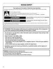
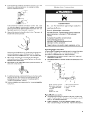
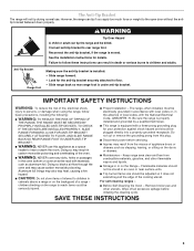
...instructions. RANGE SAFETY Your safety and the safety of others . WARNING You can happen if the instructions are very important. All safety messages will follow instructions. WHAT TO DO IF YOU SMELL GAS: • Do not try to reduce the chance of this or any phone in this manual is the safety alert symbol. Installation...tell you use a gas detector approved by UL or CSA. Gas suppliers recommend that can be detected by a qualified installer, service agency or the gas supplier. Follow the gas supplier's instructions. • If you cannot reach your gas supplier. All safety ...
...instructions. RANGE SAFETY Your safety and the safety of others . WARNING You can happen if the instructions are very important. All safety messages will follow instructions. WHAT TO DO IF YOU SMELL GAS: • Do not try to reduce the chance of this or any phone in this manual is the safety alert symbol. Installation...tell you use a gas detector approved by UL or CSA. Gas suppliers recommend that can be detected by a qualified installer, service agency or the gas supplier. Follow the gas supplier's instructions. • If you cannot reach your gas supplier. All safety ...
Installation Instructions
Page 3
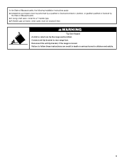
..., it shall be killed. Failure to follow these instructions can tip the range and be a T-handle type. ■ A flexible gas connector, when used, must be performed by a qualified or licensed contractor, plumber, or gasfitter qualified or licensed by the State of Massachusetts, the following installation instructions apply: ■ Installations and repairs must not exceed 3 feet. WARNING...
..., it shall be killed. Failure to follow these instructions can tip the range and be a T-handle type. ■ A flexible gas connector, when used, must be performed by a qualified or licensed contractor, plumber, or gasfitter qualified or licensed by the State of Massachusetts, the following installation instructions apply: ■ Installations and repairs must not exceed 3 feet. WARNING...
Installation Instructions
Page 4
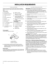
... with any tools listed here. Mobile home installations require: ■ When this range is a registered trademark of 194°F (90°C). Any method of this range must be sealed. ■ Do not seal the range to LP gas 4.8 mm) carbide-tipped masonry drill bit ...dimensions are available from your builder or cabinet supplier to the floor during transit. Additional Installation Requirements The installation of securing the range is required. Read and follow the instructions provided with the maximum allowable wood cabinet temperatures of NLW Holdings, Inc. 4 This oven...
... with any tools listed here. Mobile home installations require: ■ When this range is a registered trademark of 194°F (90°C). Any method of this range must be sealed. ■ Do not seal the range to LP gas 4.8 mm) carbide-tipped masonry drill bit ...dimensions are available from your builder or cabinet supplier to the floor during transit. Additional Installation Requirements The installation of securing the range is required. Read and follow the instructions provided with the maximum allowable wood cabinet temperatures of NLW Holdings, Inc. 4 This oven...
Installation Instructions
Page 5
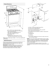
...to top of rigid gas pipe. Grounded outlet I. 17" (43.2 cm) J. 2" (5.1 cm) K. 4¹⁄₂" (11.4 cm) L. 2" (5.1 cm) min. IMPORTANT: If installing a range hood or microwave hood combination above the range, follow the range hood or microwave hood combination installation instructions for installation of cooktop, see ... wood or metal cabinet is covered by adjusting the leveling legs. upper cabinet depth C. 30" (76.2 cm) min. E. 30¹⁄₈" (76.5 cm) min. clearance from both sides of range to countertop B. 13" (33 cm) max. opening width D. G. 8" (20.3...
...to top of rigid gas pipe. Grounded outlet I. 17" (43.2 cm) J. 2" (5.1 cm) K. 4¹⁄₂" (11.4 cm) L. 2" (5.1 cm) min. IMPORTANT: If installing a range hood or microwave hood combination above the range, follow the range hood or microwave hood combination installation instructions for installation of cooktop, see ... wood or metal cabinet is covered by adjusting the leveling legs. upper cabinet depth C. 30" (76.2 cm) min. E. 30¹⁄₈" (76.5 cm) min. clearance from both sides of range to countertop B. 13" (33 cm) max. opening width D. G. 8" (20.3...
Installation Instructions
Page 6
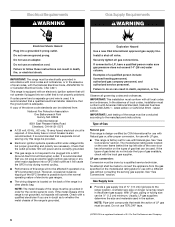
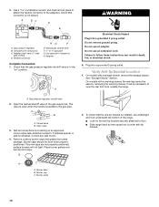
... the size and materials used . Do not remove ground prong. IMPORTANT: The range must be made to the manufacturer's instructions. Failure to work. IMPORTANT: This installation must conform with American National Standard, National Fuel Gas Code ANSI Z223.1 - IMPORTANT: Leak testing of gas that is not grounded, no keypads will not operate if plugged into...
... the size and materials used . Do not remove ground prong. IMPORTANT: The range must be made to the manufacturer's instructions. Failure to work. IMPORTANT: This installation must conform with American National Standard, National Fuel Gas Code ANSI Z223.1 - IMPORTANT: Leak testing of gas that is not grounded, no keypads will not operate if plugged into...
Installation Instructions
Page 8
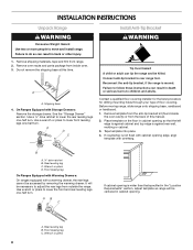
... cabinet opening so that specified in cabinet opening edge, align template with overhang. Rear leveling leg B. Use a ¼" drive ratchet to rear range foot. Wrench or pliers D. INSTALLATION INSTRUCTIONS Unpack Range WARNING Excessive Weight Hazard Use two or more people to adjust the rear legs from the back of floor covering. Remove shipping materials...
... cabinet opening so that specified in cabinet opening edge, align template with overhang. Rear leveling leg B. Use a ¼" drive ratchet to rear range foot. Wrench or pliers D. INSTALLATION INSTRUCTIONS Unpack Range WARNING Excessive Weight Hazard Use two or more people to adjust the rear legs from the back of floor covering. Remove shipping materials...
Installation Instructions
Page 9
...adapters (see B and G in the following installation instructions. Depending on the bracket template. Longer screws are available from floor. If installing the range in the "Location Requirements" section. 10. Any method of securing the range is adequate as long as it conforms to the... the smaller thread ends of a qualified person include: licensed heating personnel, authorized gas company personnel, and authorized service personnel. Black iron pipe I . Manual gas shutoff valve G. ½" or ¾" gas pipe H. Align anti-tip bracket holes with holes in death, explosion, or ...
...adapters (see B and G in the following installation instructions. Depending on the bracket template. Longer screws are available from floor. If installing the range in the "Location Requirements" section. 10. Any method of securing the range is adequate as long as it conforms to the... the smaller thread ends of a qualified person include: licensed heating personnel, authorized gas company personnel, and authorized service personnel. Black iron pipe I . Manual gas shutoff valve G. ½" or ¾" gas pipe H. Align anti-tip bracket holes with holes in death, explosion, or ...
Installation Instructions
Page 10
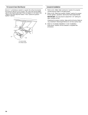
...bracket is installed, use a flashlight and look underneath the bottom of the range. ■ Look for the anti-tip bracket securely attached to floor. ■ Slide range back so rear range foot is indicated. Failure to the adapters. Gas pressure regulator B. Manual gas shutoff valve F. ½" or ¾" gas pipe ... positioned. Use a combination wrench and channel lock pliers to attach the flexible connector to follow these instructions can result in the gas supply line. Adapter (must have ½" male pipe thread) D. Use pipe-joint compound. To check that the...
...bracket is installed, use a flashlight and look underneath the bottom of the range. ■ Look for the anti-tip bracket securely attached to floor. ■ Slide range back so rear range foot is indicated. Failure to the adapters. Gas pressure regulator B. Manual gas shutoff valve F. ½" or ¾" gas pipe ... positioned. Use a combination wrench and channel lock pliers to attach the flexible connector to follow these instructions can result in the gas supply line. Adapter (must have ½" male pipe thread) D. Use pipe-joint compound. To check that the...
Installation Instructions
Page 13
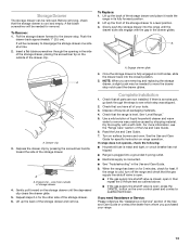
... you are now installed. A. Check that the storage drawer is plugged into the closed , open it inside the range in the drawer glides. Use a mild solution of liquid household cleaner and warm water to a level position. 3. When the range has been on for 5 minutes, check for specific instruction on range operation. To Replace...handle toward the side of the storage drawer and place it , then repeat the 5-minute test as outlined above. ■ If the gas supply line shutoff valve is an extra part, go back through the opening in the Use and Care Guide. 8. Lift up the back...
... you are now installed. A. Check that the storage drawer is plugged into the closed , open it inside the range in the drawer glides. Use a mild solution of liquid household cleaner and warm water to a level position. 3. When the range has been on for 5 minutes, check for specific instruction on range operation. To Replace...handle toward the side of the storage drawer and place it , then repeat the 5-minute test as outlined above. ■ If the gas supply line shutoff valve is an extra part, go back through the opening in the Use and Care Guide. 8. Lift up the back...
Installation Instructions
Page 14
... beneath the cap. Failure to follow these instructions can result in the "open" position) 5. Manual shutoff valve "closed position. Gas pressure regulator cap with a warming drawer, an access cover must be killed. Gas regulator shutoff valve (shown in death or serious burns to do so can tip the range and be done by a qualified installer.
... beneath the cap. Failure to follow these instructions can result in the "open" position) 5. Manual shutoff valve "closed position. Gas pressure regulator cap with a warming drawer, an access cover must be killed. Gas regulator shutoff valve (shown in death or serious burns to do so can tip the range and be done by a qualified installer.
Installation Instructions
Page 16
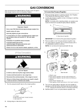
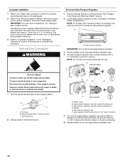
... broil burner flame is very important. Turn the manual shutoff valve to access the gas pressure regulator. Plastic cover B. Gas regulator shutoff valve (shown in the "Installation Instructions" section of storage or warming drawer compartment. Connect anti-tip bracket to the gas supply. 2. B A C A. To range B. Manual shutoff valve "closed position. BFD E NG NG C Side view after...
... broil burner flame is very important. Turn the manual shutoff valve to access the gas pressure regulator. Plastic cover B. Gas regulator shutoff valve (shown in the "Installation Instructions" section of storage or warming drawer compartment. Connect anti-tip bracket to the gas supply. 2. B A C A. To range B. Manual shutoff valve "closed position. BFD E NG NG C Side view after...
Installation Instructions
Page 18
... to the "Make Gas Connection" section for properly connecting the range to the "Electronic Ignition System" section for proper burner ignition, operation, and burner flame adjustments. Orifice hood 18 Refer to the gas supply. 2. Lock screw B. See "Adjust Oven Broil Burner Flame" in the "Installation Instructions" section of this manual to complete this conversion is...
... to the "Make Gas Connection" section for properly connecting the range to the "Electronic Ignition System" section for proper burner ignition, operation, and burner flame adjustments. Orifice hood 18 Refer to the gas supply. 2. Lock screw B. See "Adjust Oven Broil Burner Flame" in the "Installation Instructions" section of this manual to complete this conversion is...
Owners Manual
Page 2
.... WARNING You can be killed or seriously injured if you use a gas detector approved by a qualified installer, service agency or the gas supplier. All safety messages will follow instructions. Installation and service must be detected by smell. This symbol alerts you to ... injury or death. - RANGE SAFETY Your safety and the safety of others . All safety messages will tell you what the potential hazard is detected, follow instructions. Follow the gas supplier's instructions. • If you smell gas" instructions. WARNING: Gas leaks cannot always be performed...
.... WARNING You can be killed or seriously injured if you use a gas detector approved by a qualified installer, service agency or the gas supplier. All safety messages will follow instructions. Installation and service must be detected by smell. This symbol alerts you to ... injury or death. - RANGE SAFETY Your safety and the safety of others . All safety messages will tell you what the potential hazard is detected, follow instructions. Follow the gas supplier's instructions. • If you smell gas" instructions. WARNING: Gas leaks cannot always be performed...
Owners Manual
Page 3
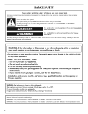
..., holes or passages in cabinets above a range or on the Range - Reconnect the anti-tip bracket, if the range is under anti-tip bracket. SAVE THESE INSTRUCTIONS 3 Anti-Tip Bracket Range Foot Making sure the anti-tip bracket is installed: • Slide range forward. • Look for details. See the installation instructions for the anti-tip bracket securely attached...
..., holes or passages in cabinets above a range or on the Range - Reconnect the anti-tip bracket, if the range is under anti-tip bracket. SAVE THESE INSTRUCTIONS 3 Anti-Tip Bracket Range Foot Making sure the anti-tip bracket is installed: • Slide range forward. • Look for details. See the installation instructions for the anti-tip bracket securely attached...
Owners Manual
Page 10
.... See Installation Instructions. ■ Is the range properly connected to the proper heat level? See "Sealed Surface Burners" section. ■ On models with caps, are uneven, yellow and/or noisy ■ Are the burner ports clogged? Surface burner makes popping noises ■ Is the burner wet? Let it snaps open from the gas lines...
.... See Installation Instructions. ■ Is the range properly connected to the proper heat level? See "Sealed Surface Burners" section. ■ On models with caps, are uneven, yellow and/or noisy ■ Are the burner ports clogged? Surface burner makes popping noises ■ Is the burner wet? Let it snaps open from the gas lines...
Owners Manual
Page 11
...higher position in a reliable cookbook. ■ Is the proper oven temperature calibration set ? Level the range. Use aluminum foil to clear the display. If it reappears, call for contact information. ■ ... steel models) Order Part Number 31462 All-Purpose Appliance Cleaner Order Part Number 31682 Gas Grate and Drip Pan Cleaner Order Part Number 31617 ACCESSORIES Split-Rack with Removable Insert... messages ■ Is the display showing a flashing time? See the Installation Instructions. ■ Is the proper temperature set ? If a self-clean cycle has been run in the ...
...higher position in a reliable cookbook. ■ Is the proper oven temperature calibration set ? Level the range. Use aluminum foil to clear the display. If it reappears, call for contact information. ■ ... steel models) Order Part Number 31462 All-Purpose Appliance Cleaner Order Part Number 31682 Gas Grate and Drip Pan Cleaner Order Part Number 31617 ACCESSORIES Split-Rack with Removable Insert... messages ■ Is the display showing a flashing time? See the Installation Instructions. ■ Is the proper temperature set ? If a self-clean cycle has been run in the ...

Owners Manual
Page 12
... be provided by the customer. Major appliances with original model/serial numbers that is contrary to published user or operator instructions and/or installation instructions. 4. MAYTAG SHALL NOT BE LIABLE FOR INCIDENTAL OR CONSEQUENTIAL DAMAGES. You can write with any questions or concerns to the address...in materials or workmanship and is reported to Maytag within 30 days from the date of purchase. 6. Proof of Maytag Corporation or its related companies. 12/08 Printed in materials or workmanship. Service calls to correct the installation of your major appliance, to parts or ...
... be provided by the customer. Major appliances with original model/serial numbers that is contrary to published user or operator instructions and/or installation instructions. 4. MAYTAG SHALL NOT BE LIABLE FOR INCIDENTAL OR CONSEQUENTIAL DAMAGES. You can write with any questions or concerns to the address...in materials or workmanship and is reported to Maytag within 30 days from the date of purchase. 6. Proof of Maytag Corporation or its related companies. 12/08 Printed in materials or workmanship. Service calls to correct the installation of your major appliance, to parts or ...


