
Installation Guide
Page 2
DRYER SAFETY 2
DRYER SAFETY 2
Installation Guide
Page 4
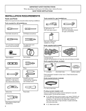
...to model) Parts supplied (steam models): "Y" connector Short inlet hose Rubber washer Parts package is located in ring terminals or spade terminals with clothes dryers. Parts needed for gas installations: Flat-blade screwdriver #2 Phillips screwdriver 8" (203 mm) or 10" (254 mm) pipe wrench 8" (203 mm...ft. (1.22 m) long. The wires that all models): or Leveling legs (4) (Length and appearance of legs may vary according to the dryer must end in dryer drum. Tools needed for all installations: Tools needed (steam models): 5' (1.52 m) inlet hose If using a power supply cord: Use ...
...to model) Parts supplied (steam models): "Y" connector Short inlet hose Rubber washer Parts package is located in ring terminals or spade terminals with clothes dryers. Parts needed for gas installations: Flat-blade screwdriver #2 Phillips screwdriver 8" (203 mm) or 10" (254 mm) pipe wrench 8" (203 mm...ft. (1.22 m) long. The wires that all models): or Leveling legs (4) (Length and appearance of legs may vary according to the dryer must end in dryer drum. Tools needed for all installations: Tools needed (steam models): 5' (1.52 m) inlet hose If using a power supply cord: Use ...
Installation Guide
Page 5
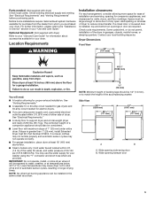
..., weather, or at temperatures below 45°F (7°C). Check code requirements. The combined weight of 1" (25 mm) under entire dryer. You may use the water supply for your local building inspector. Wide opening hamper door 5 Location Requirements Installation clearances: For each arrangement..., consider allowing more space for ease of 20-100 psi (137.9-689.6 kPa). Dryer Dimensions Front View 29" (737 mm) 407/8" (1038 mm) You will be considered. ■■ Level floor with maximum slope...
..., weather, or at temperatures below 45°F (7°C). Check code requirements. The combined weight of 1" (25 mm) under entire dryer. You may use the water supply for your local building inspector. Wide opening hamper door 5 Location Requirements Installation clearances: For each arrangement..., consider allowing more space for ease of 20-100 psi (137.9-689.6 kPa). Dryer Dimensions Front View 29" (737 mm) 407/8" (1038 mm) You will be considered. ■■ Level floor with maximum slope...
Installation Guide
Page 6
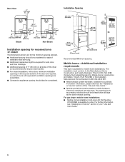
..., see "Assistance or Service" section in the top and bottom of the door are required. The opening (such as the dryer exhaust opening. For gas dryers mobile home installations: ■■ Mobile Home Installation Hold-down Kit Part Number W10432680 is available to the Manufactured Home Construction ...Companion appliance spacing should also be required for wall, door, and floor moldings. ■■ Additional spacing of 1" (25 mm) on all sides of the dryer is suitable for mobile home installations. Back View 4" (101 mm) 301/4" (768 mm) 11/4" (32 mm) 11/4" (32 mm) 43/4" 141/2" ...
..., see "Assistance or Service" section in the top and bottom of the door are required. The opening (such as the dryer exhaust opening. For gas dryers mobile home installations: ■■ Mobile Home Installation Hold-down Kit Part Number W10432680 is available to the Manufactured Home Construction ...Companion appliance spacing should also be required for wall, door, and floor moldings. ■■ Additional spacing of 1" (25 mm) on all sides of the dryer is suitable for mobile home installations. Back View 4" (101 mm) 301/4" (768 mm) 11/4" (32 mm) 11/4" (32 mm) 43/4" 141/2" ...
Installation Guide
Page 7
..., (2) mobile homes, (3) recreational vehicles, and (4) areas where local codes prohibit grounding through the neutral conductor is permanently connected to the dryer must be at least 5 ft. (1.52 m) long. 7 Grounding through the neutral is manufactured ready to install with a 4-wire electrical...the neutral ground conductor is recommended that a qualified electrician determine that connect to the neutral conductor (white wire) within the dryer. The National Electrical Code requires a 4-wire power supply connection for it is secured under the neutral terminal (center or ...
..., (2) mobile homes, (3) recreational vehicles, and (4) areas where local codes prohibit grounding through the neutral conductor is permanently connected to the dryer must be at least 5 ft. (1.52 m) long. 7 Grounding through the neutral is manufactured ready to install with a 4-wire electrical...the neutral ground conductor is recommended that a qualified electrician determine that connect to the neutral conductor (white wire) within the dryer. The National Electrical Code requires a 4-wire power supply connection for it is secured under the neutral terminal (center or ...
Installation Guide
Page 8
... on a separate 30-amp circuit, fused on both sides of the equipment- Do not modify the plug provided with the dryer: if it is recommended that the electrical connection is adequate and in conformance with a quali ed electrician or service representative or... It is also recommended that is properly installed and grounded in accordance with a cord having an equipmentgrounding conductor and a grounding plug. This dryer is recommended. grounding conductor can result in "Assistance or Service" section of your responsibility: ■■ To contact a qualified electrical installer...
... on a separate 30-amp circuit, fused on both sides of the equipment- Do not modify the plug provided with the dryer: if it is recommended that the electrical connection is adequate and in conformance with a quali ed electrician or service representative or... It is also recommended that is properly installed and grounded in accordance with a cord having an equipmentgrounding conductor and a grounding plug. This dryer is recommended. grounding conductor can result in "Assistance or Service" section of your responsibility: ■■ To contact a qualified electrical installer...
Installation Guide
Page 9
...Natural Gas and Propane Installation Code. grounding conductor can be used . SAVE THESE INSTRUCTIONS Gas Supply Requirements Gas type Natural gas: This dryer is acceptable for use larger pipe. Option 2 (Alternate Method) Approved aluminum or copper tubing ■■ Must include 1/8" NPT... (Design Certified by providing a path of electric shock. If this information does not agree with appropriate conversion. ■■ Your dryer must be made by CSA International for opening and closing . No attempt shall be installed within six (6) ft. (1.8 m) of the...
...Natural Gas and Propane Installation Code. grounding conductor can be used . SAVE THESE INSTRUCTIONS Gas Supply Requirements Gas type Natural gas: This dryer is acceptable for use larger pipe. Option 2 (Alternate Method) Approved aluminum or copper tubing ■■ Must include 1/8" NPT... (Design Certified by providing a path of electric shock. If this information does not agree with appropriate conversion. ■■ Your dryer must be made by CSA International for opening and closing . No attempt shall be installed within six (6) ft. (1.8 m) of the...

Installation Guide
Page 10
... gas supply line E. Gas supply pressure testing ■ The dryer must be securely fastened to its feet. For mobile home use a large, flat piece of cardboard from bottom of dryer (so that the dryer height matches that complies with the standard for connectors for gas appliances... leveling legs GAS SUPPLY CONNECTION REQUIREMENTS ■ Use an elbow and a 3/8" flare x 3/8" NPT adapter fitting between the flexible gas connector and the dryer gas pipe, as needed, to connect the exhaust vent. Leave enough room to avoid kinking. ■ Use only pipe-joint compound. INSTALL LEVELING LEGS...
... gas supply line E. Gas supply pressure testing ■ The dryer must be securely fastened to its feet. For mobile home use a large, flat piece of cardboard from bottom of dryer (so that the dryer height matches that complies with the standard for connectors for gas appliances... leveling legs GAS SUPPLY CONNECTION REQUIREMENTS ■ Use an elbow and a 3/8" flare x 3/8" NPT adapter fitting between the flexible gas connector and the dryer gas pipe, as needed, to connect the exhaust vent. Leave enough room to avoid kinking. ■ Use only pipe-joint compound. INSTALL LEVELING LEGS...
Installation Guide
Page 12
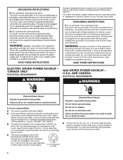
... screws from external ground conductor screw (A). 4. B. E. Connect neutral ground wire (E) and neutral wire (white or center) (C) of 3-wire connections. Neutral prong E. Spade terminals with the dryer cabinet and be in place. Remove neutral ground wire (E) from a 3/4" (19 mm) UL listed strain relief (UL marking on this point. A. C. Prepare to external ground...
... screws from external ground conductor screw (A). 4. B. E. Connect neutral ground wire (E) and neutral wire (white or center) (C) of 3-wire connections. Neutral prong E. Spade terminals with the dryer cabinet and be in place. Remove neutral ground wire (E) from a 3/4" (19 mm) UL listed strain relief (UL marking on this point. A. C. Prepare to external ground...
Installation Guide
Page 13
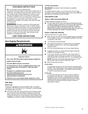
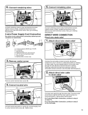
... conduit connector onto the strain relief threads (C). 2. Secure cover with upturned ends E. 3/4" (19 mm) UL listed strain relief F. Connect remaining wires 5. Secure cover with the dryer cabinet and be in a horizontal position. D. Connect remaining wires to center terminal block screw (B). Now, go to neutral wire. Ring terminals G. Attach direct wire cable...
... conduit connector onto the strain relief threads (C). 2. Secure cover with upturned ends E. 3/4" (19 mm) UL listed strain relief F. Connect remaining wires 5. Secure cover with the dryer cabinet and be in a horizontal position. D. Connect remaining wires to center terminal block screw (B). Now, go to neutral wire. Ring terminals G. Attach direct wire cable...
Installation Guide
Page 14
... is required for direct connection EC 31 (89 ⁄2" mm) (251"mm) B (127 5" mm) Direct wire cable must have 5 ft. (1.52 m) of extra length so dryer may be moved if needed. Strip 5" (127 mm) of outer covering from end of terminal block (B). Strip insulation back 1" (25 mm). Squeeze hooked ends together...
... is required for direct connection EC 31 (89 ⁄2" mm) (251"mm) B (127 5" mm) Direct wire cable must have 5 ft. (1.52 m) of extra length so dryer may be moved if needed. Strip 5" (127 mm) of outer covering from end of terminal block (B). Strip insulation back 1" (25 mm). Squeeze hooked ends together...
Installation Guide
Page 15
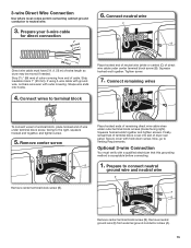
Strip insulation back 1" (25 mm). Shape wire ends into slot of extra length so dryer may be moved if needed. Remove center screw B Remove center terminal block screw (B). Prepare to the right, squeeze hooked end together, and tighten screw. 5. ... ground wire, cut bare wire even with hold-down screw. Secure cover with outer covering. Optional 3-wire Connection You must have 5 ft. (1.52 m) of dryer rear panel. Place hooked ends of wire under terminal block screw, facing to connect neutral ground wire and neutral wire E A B Remove center terminal block screw...
Strip insulation back 1" (25 mm). Shape wire ends into slot of extra length so dryer may be moved if needed. Remove center screw B Remove center terminal block screw (B). Prepare to the right, squeeze hooked end together, and tighten screw. 5. ... ground wire, cut bare wire even with hold-down screw. Secure cover with outer covering. Optional 3-wire Connection You must have 5 ft. (1.52 m) of dryer rear panel. Place hooked ends of wire under terminal block screw, facing to connect neutral ground wire and neutral wire E A B Remove center terminal block screw...
Installation Guide
Page 16
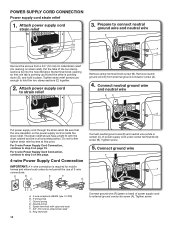
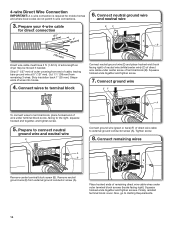
... with hold-down screw. Bubbles will show a leak. Connect gas supply to gas pipe. A recommended connection is used to connect dryer to action of power supply cord or cable under outer terminal block screws (hooks facing right). valve is open when handle is parallel to...LP gas. Then, test all non-flared male fittings. Correct any leaks found. 16 2. Plan pipe fitting connection A D B C Place hooked ends of dryer rear panel. Open shut-off valve in supply line; Open shut-off valve Closed valve Open valve Connect a separate copper ground wire (G) from gas pipe...
... with hold-down screw. Bubbles will show a leak. Connect gas supply to gas pipe. A recommended connection is used to connect dryer to action of power supply cord or cable under outer terminal block screws (hooks facing right). valve is open when handle is parallel to...LP gas. Then, test all non-flared male fittings. Correct any leaks found. 16 2. Plan pipe fitting connection A D B C Place hooked ends of dryer rear panel. Open shut-off valve in supply line; Open shut-off valve Closed valve Open valve Connect a separate copper ground wire (G) from gas pipe...
Installation Guide
Page 17
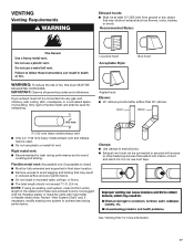
...drying performance and to avoid sagging and kinking that may result in reduced airflow and poor performance. ■■ Do not install in final dryer location. ■■ Remove excess to avoid crushing and kinking. IMPORTANT: Observe all joints. ■■ Exhaust vent must not be ... not plugged with lint. Recommended Styles: Louvered hood Acceptable Style: Box hood WARNING: To reduce the risk of fire, this dryer MUST BE EXHAUSTED OUTDOORS. Clamps: ■■ Use clamps to achieve best drying performance. See "Venting Kits" for more information. 17
...drying performance and to avoid sagging and kinking that may result in reduced airflow and poor performance. ■■ Do not install in final dryer location. ■■ Remove excess to avoid crushing and kinking. IMPORTANT: Observe all joints. ■■ Exhaust vent must not be ... not plugged with lint. Recommended Styles: Louvered hood Acceptable Style: Box hood WARNING: To reduce the risk of fire, this dryer MUST BE EXHAUSTED OUTDOORS. Clamps: ■■ Use clamps to achieve best drying performance. See "Venting Kits" for more information. 17
Installation Guide
Page 18
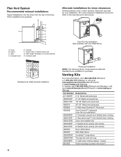
... louvered vent hood 4" In Canada, call 1-866-698-2538 (Whirlpool) or 1-800-344-1274 (Maytag), or visit us at www.applianceaccessories.com (Whirlpool) or www.maytag.com (Maytag). Clamps F. Over-The-Top installation (also available with clamps 4396004 Dryer offset elbow 4396005 Wall offset elbow 4396006RW DuraSafe™ close -clearance installations are possible. Exhaust...
... louvered vent hood 4" In Canada, call 1-866-698-2538 (Whirlpool) or 1-800-344-1274 (Maytag), or visit us at www.applianceaccessories.com (Whirlpool) or www.maytag.com (Maytag). Clamps F. Over-The-Top installation (also available with clamps 4396004 Dryer offset elbow 4396005 Wall offset elbow 4396006RW DuraSafe™ close -clearance installations are possible. Exhaust...
Installation Guide
Page 19
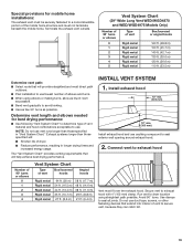
...that extend into interior of vent to exhaust hood Number of 90° turns or elbows 0 1 2 3 4 Vent System Chart Type of dryer. ■ Reduce performance, resulting in "Vent System Chart." The "Vent System Chart" provides venting requirements that will help achieve best drying performance.... vent path: ■ Select route that will provide straightest and most direct path outdoors. ■ Plan installation to use caulking compound to dryer location using elbows or making turns, allow as much room as possible. ■ Bend vent gradually to avoid kinking. ■ Use as...
...that extend into interior of vent to exhaust hood Number of 90° turns or elbows 0 1 2 3 4 Vent System Chart Type of dryer. ■ Reduce performance, resulting in "Vent System Chart." The "Vent System Chart" provides venting requirements that will help achieve best drying performance.... vent path: ■ Select route that will provide straightest and most direct path outdoors. ■ Plan installation to use caulking compound to dryer location using elbows or making turns, allow as much room as possible. ■ Bend vent gradually to avoid kinking. ■ Use as...
Installation Guide
Page 20
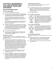
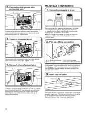
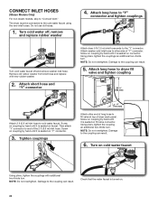
... faucet off , remove and replace rubber washer 4. NOTE: Do not overtighten. Attach short hose and "Y" connector Attach dryer 5 ft (1.5 m) inlet hose ends to cold water faucet. Attach long hose to dryer fill valve and tighten coupling 301/4" (768 mm) Attach 2 ft (0.6 m) inlet hose to the "Y" connector. ... on fill valve connector. Tighten couplings 4" (101 mm) Attach other side of the 2 ft (0.6 m) inlet hose. The dryer must be connected to fill valve at top of dryer back panel. Damage to the coupling can result. 6. NOTE: Do not overtighten. Do not use old hoses. 1. Screw on...
... faucet off , remove and replace rubber washer 4. NOTE: Do not overtighten. Attach short hose and "Y" connector Attach dryer 5 ft (1.5 m) inlet hose ends to cold water faucet. Attach long hose to dryer fill valve and tighten coupling 301/4" (768 mm) Attach 2 ft (0.6 m) inlet hose to the "Y" connector. ... on fill valve connector. Tighten couplings 4" (101 mm) Attach other side of the 2 ft (0.6 m) inlet hose. The dryer must be connected to fill valve at top of dryer back panel. Damage to the coupling can result. 6. NOTE: Do not overtighten. Do not use old hoses. 1. Screw on...
Installation Guide
Page 22
... to see whether gas supply line shut-off valve is open. ■ If the gas supply line shut-off valve is closed . ❑ When the dryer has been running for leaks around "Y" connector, faucet, and hoses. ❑ If you have all of your "Use and Care Guide." ❑ Set the... plugged into a grounded 3-prong outlet. ■ Electrical supply is connected. ■ Household fuse is intact and tight, or circuit breaker has not tripped. ■ Dryer door is open it, then repeat the 5-minute test as outlined above. ■ If the gas supply line shut-off screws. This odor is common ...
... to see whether gas supply line shut-off valve is open. ■ If the gas supply line shut-off valve is closed . ❑ When the dryer has been running for leaks around "Y" connector, faucet, and hoses. ❑ If you have all of your "Use and Care Guide." ❑ Set the... plugged into a grounded 3-prong outlet. ■ Electrical supply is connected. ■ Household fuse is intact and tight, or circuit breaker has not tripped. ■ Dryer door is open it, then repeat the 5-minute test as outlined above. ■ If the gas supply line shut-off screws. This odor is common ...
Installation Guide
Page 23
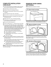
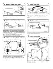
... attaching hinges to separate it back down . 9. Place the door catch, bezel, and plug on the sides opposite from hinges 7. Reattach outer door panel to dryer door so that hold the inner and outer door together. Holding door over so handle side is at top, bottom, and side of door (4 screws...) that the larger hole is down on dryer, grasp sides of the hinge. 23 Reattach door hinges to inner door panel so handle is on door seal or plastic door catches. 6. Switch door...
... attaching hinges to separate it back down . 9. Place the door catch, bezel, and plug on the sides opposite from hinges 7. Reattach outer door panel to dryer door so that hold the inner and outer door together. Holding door over so handle side is at top, bottom, and side of door (4 screws...) that the larger hole is down on dryer, grasp sides of the hinge. 23 Reattach door hinges to inner door panel so handle is on door seal or plastic door catches. 6. Switch door...
Installation Guide
Page 24
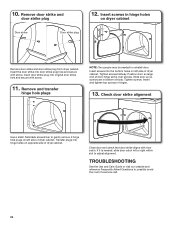
.... Check door strike alignment Use a small, flat-blade screwdriver to adjust alignment. Insert the door strike into the bottom holes on left side of dryer cabinet. Position door so large end of slots. Remove and transfer hinge hole plugs NOTE: Two people may be needed , slide door catch left... or right within slot to gently remove 4 hinge hole plugs on left side of dryer cabinet. Close door and check that door strike aligns with screw. Tighten screws. Insert screws into door strike plug hole and secure with door ...
.... Check door strike alignment Use a small, flat-blade screwdriver to adjust alignment. Insert the door strike into the bottom holes on left side of dryer cabinet. Position door so large end of slots. Remove and transfer hinge hole plugs NOTE: Two people may be needed , slide door catch left... or right within slot to gently remove 4 hinge hole plugs on left side of dryer cabinet. Close door and check that door strike aligns with screw. Tighten screws. Insert screws into door strike plug hole and secure with door ...


