Owners Manual
Page 6
...be adjusted so it does not extend beyond the edge of the gas flame. Left front burner (9,200 BTUs). 4. Right front burner (12,500 BTUs). Since the burners are acceptable. If using natural gas, the flame will vary when using LP gas. Surface Cooking, cont. Left front burner (9,200 BTUs). 2....porcelain finish may discolor the surface. Sealed Burners The sealed burners are secured to the cooktop and are not designed to adjust. (Adjustments are not covered by the warranty.) With LP gas, some types of gas, you may result in the right front position. Contact a service technician to be ...
...be adjusted so it does not extend beyond the edge of the gas flame. Left front burner (9,200 BTUs). 4. Right front burner (12,500 BTUs). Since the burners are acceptable. If using natural gas, the flame will vary when using LP gas. Surface Cooking, cont. Left front burner (9,200 BTUs). 2....porcelain finish may discolor the surface. Sealed Burners The sealed burners are secured to the cooktop and are not designed to adjust. (Adjustments are not covered by the warranty.) With LP gas, some types of gas, you may result in the right front position. Contact a service technician to be ...
Installation Instructions
Page 1
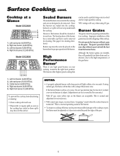
INSTALLATION MANUAL SEALED GAS COOKTOPS 30" and 36" IMPORTANT: Dimensions Shown in Both Inches and Centimeters. NOTICE TO INSTALLER: Leave these instructions for use with the appliance. W10187822 (01-08-00) NOTICE TO CONSUMER: Retain these instructions with a gas other than the type specified. 30″ MODEL DIMENSIONS inches cm A 28 1/2 + 1/16 72.4 + 0.2 B 19 15/16 + 1/16 50...
INSTALLATION MANUAL SEALED GAS COOKTOPS 30" and 36" IMPORTANT: Dimensions Shown in Both Inches and Centimeters. NOTICE TO INSTALLER: Leave these instructions for use with the appliance. W10187822 (01-08-00) NOTICE TO CONSUMER: Retain these instructions with a gas other than the type specified. 30″ MODEL DIMENSIONS inches cm A 28 1/2 + 1/16 72.4 + 0.2 B 19 15/16 + 1/16 50...
Installation Instructions
Page 8
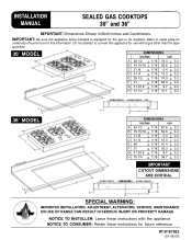
... burner flame at medium setting. Carefully remove rubber grommet. 3. Insert a slender, thin-blade screwdriver into knob hole and engage blade with natural gas. FIGURE 10 C. IF KNOB CANNOT BE EASILY REMOVED, TUCK THE FOLDS OF A CLOTH DISHTOWEL UNDER THE KNOB AND PULL THE TOWEL UPWARD WITH... minimum size. Do not over tighten. 6. This operation will automatically provide the proper flame size at the Hi and Lo settings against figure 12. Turn the adjusting screw clockwise until tight (5-7 in adjusting screw. 5. The setting should produce a stable, steady blue flame of each step...
... burner flame at medium setting. Carefully remove rubber grommet. 3. Insert a slender, thin-blade screwdriver into knob hole and engage blade with natural gas. FIGURE 10 C. IF KNOB CANNOT BE EASILY REMOVED, TUCK THE FOLDS OF A CLOTH DISHTOWEL UNDER THE KNOB AND PULL THE TOWEL UPWARD WITH... minimum size. Do not over tighten. 6. This operation will automatically provide the proper flame size at the Hi and Lo settings against figure 12. Turn the adjusting screw clockwise until tight (5-7 in adjusting screw. 5. The setting should produce a stable, steady blue flame of each step...
Installation Instructions
Page 9
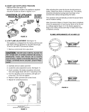
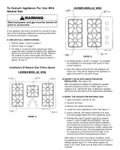
...checked by turning the knob from the appliance for use . Observe the number on figure 12. Installation Of Natural Gas Orifice Spuds 5 BURNER MODEL (36″ WIDE) 1.55 1.42 1.42 1.42 1.61 FIGURE 13 4 BURNER MODEL (30″ WIDE) 1.55 1.55 1.55 1.85 FIGURE 14 4. Insert a slender, thin...before its conversion for each burner's flame at the Hi and Lo settings against figure 12. Light one burner, and set on page 7 to natural gas. See figure 11. 5. RESET THE VALVES FOR NATURAL GAS 1. They will produce a stable, steady blue flame of appliance regulator and follow ...
...checked by turning the knob from the appliance for use . Observe the number on figure 12. Installation Of Natural Gas Orifice Spuds 5 BURNER MODEL (36″ WIDE) 1.55 1.42 1.42 1.42 1.61 FIGURE 13 4 BURNER MODEL (30″ WIDE) 1.55 1.55 1.55 1.85 FIGURE 14 4. Insert a slender, thin...before its conversion for each burner's flame at the Hi and Lo settings against figure 12. Light one burner, and set on page 7 to natural gas. See figure 11. 5. RESET THE VALVES FOR NATURAL GAS 1. They will produce a stable, steady blue flame of appliance regulator and follow ...
Installation Instructions
Page 10
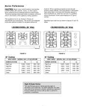
... a qualified service technician. NATURAL GAS / LP GAS (BTU/HR) BURNER LOCATION Right Front Right Rear Left Front Left Rear Center Hi 12,500 / 10,500 9,200 / 9,100 9,200 / 9,100 10,500 / 9,100 9,200 / 9,100 Lo 1300 / 1300 1300 / 1300 1300 / 1300 1300 / 1300 1300 / 1300 FIGURE 16 30″ Cooktop INPUT RATES - Never obstruct free...
... a qualified service technician. NATURAL GAS / LP GAS (BTU/HR) BURNER LOCATION Right Front Right Rear Left Front Left Rear Center Hi 12,500 / 10,500 9,200 / 9,100 9,200 / 9,100 10,500 / 9,100 9,200 / 9,100 Lo 1300 / 1300 1300 / 1300 1300 / 1300 1300 / 1300 1300 / 1300 FIGURE 16 30″ Cooktop INPUT RATES - Never obstruct free...