Owners Manual
Page 1
Important Safety Instructions . .1-3 Surface Cooking 4-5 Model Number Serial Number Date of purchase. All rights reserved. TTY for future reference. Printed in U.S.A. U ' G SER S PRECAUCIÓN UIDE Gas Cooktop Installer: Please leave this manual with this guide. Keep sales receipt and/or cancelled check as proof ... 8 am-8 pm Eastern Time) For service information, see page 7. A/01/08 Part No. 8111P524-60 © 2006 Maytag Appliances Sales Co. Table of our cooking products, it may be necessary to make changes to the appliance without revising this appliance.
Important Safety Instructions . .1-3 Surface Cooking 4-5 Model Number Serial Number Date of purchase. All rights reserved. TTY for future reference. Printed in U.S.A. U ' G SER S PRECAUCIÓN UIDE Gas Cooktop Installer: Please leave this manual with this guide. Keep sales receipt and/or cancelled check as proof ... 8 am-8 pm Eastern Time) For service information, see page 7. A/01/08 Part No. 8111P524-60 © 2006 Maytag Appliances Sales Co. Table of our cooking products, it may be necessary to make changes to the appliance without revising this appliance.
Owners Manual
Page 6
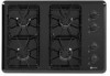
... seconds. NOTES: • A properly adjusted burner with a deeper blue inner cone. If using LP gas. Model CGC2536 1 2 3 4 5 1. Left front burner (9,200 BTUs). 2. To prevent the cooktop from the burner flame. High Performance Burner* There is noisy, the air/gas mixture may be blue with clean ports will be incorrect. The grate's porcelain finish may...
... seconds. NOTES: • A properly adjusted burner with a deeper blue inner cone. If using LP gas. Model CGC2536 1 2 3 4 5 1. Left front burner (9,200 BTUs). 2. To prevent the cooktop from the burner flame. High Performance Burner* There is noisy, the air/gas mixture may be blue with clean ports will be incorrect. The grate's porcelain finish may...
Owners Manual
Page 7
...the surface burner will not light if ignitor is correctly rated for 30 minutes. If soil remains, reapply Cooktop Cleaning Creme, cover with a damp paper towel and soak for your...dry. • Wash, rinse and dry. COOKTOP - All spillovers, especially acidic or sugary spillovers, should be sure plug is dry and clicking. STAINLESS STEEL (SELECT MODELS) • DO NOT USE ANY CLEANING ...cap is correctly seated on the burner base. • Check that the gas supply is sitting on exterior finish of cooktop. Burner will not light. • Toensureevencookingperformance,keep burner ports free of ...
...the surface burner will not light if ignitor is correctly rated for 30 minutes. If soil remains, reapply Cooktop Cleaning Creme, cover with a damp paper towel and soak for your...dry. • Wash, rinse and dry. COOKTOP - All spillovers, especially acidic or sugary spillovers, should be sure plug is dry and clicking. STAINLESS STEEL (SELECT MODELS) • DO NOT USE ANY CLEANING ...cap is correctly seated on the burner base. • Check that the gas supply is sitting on exterior finish of cooktop. Burner will not light. • Toensureevencookingperformance,keep burner ports free of ...
Owners Manual
Page 8
... to the appliance. 9. Outside the 50 United States and Canada, this limited warranty does not apply. Costs associated with original model/serial numbers that is contrary to correct defects in materials or workmanship and is reported to determine if another warranty applies. If ... is installed in an inaccessible location or is not installed in accordance with electrical or plumbing codes, or use your authorized Maytag dealer to Maytag within 30 days from the date of purchase. 6. The cost of repair or replacement under this limited warranty. After checking "Troubleshooting...
... to the appliance. 9. Outside the 50 United States and Canada, this limited warranty does not apply. Costs associated with original model/serial numbers that is contrary to correct defects in materials or workmanship and is reported to determine if another warranty applies. If ... is installed in an inaccessible location or is not installed in accordance with electrical or plumbing codes, or use your authorized Maytag dealer to Maytag within 30 days from the date of purchase. 6. The cost of repair or replacement under this limited warranty. After checking "Troubleshooting...
Installation Instructions
Page 1
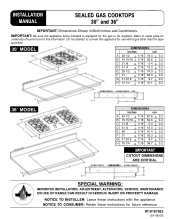
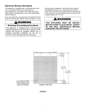
... serial plate on underside of burner box for this appliance for use with the appliance. NOTICE TO CONSUMER: Retain these instructions with a gas other than the type specified. 30″ MODEL DIMENSIONS inches cm A 28 1/2 + 1/16 72.4 + 0.2 B 19 15/16 + 1/16 50.6 + 0.2 C 2 1/8 + 1/16 5.4 + 0.2 D 5 1/4 + 1/16 13.3 + 0.2 E 29 ... Leave these instructions for the gas to be supplied. IMPORTANT: Be sure the appliance being installed is equipped for future reference. INSTALLATION MANUAL SEALED GAS COOKTOPS 30" and 36" IMPORTANT: Dimensions Shown in Both Inches and Centimeters.
... serial plate on underside of burner box for this appliance for use with the appliance. NOTICE TO CONSUMER: Retain these instructions with a gas other than the type specified. 30″ MODEL DIMENSIONS inches cm A 28 1/2 + 1/16 72.4 + 0.2 B 19 15/16 + 1/16 50.6 + 0.2 C 2 1/8 + 1/16 5.4 + 0.2 D 5 1/4 + 1/16 13.3 + 0.2 E 29 ... Leave these instructions for the gas to be supplied. IMPORTANT: Be sure the appliance being installed is equipped for future reference. INSTALLATION MANUAL SEALED GAS COOKTOPS 30" and 36" IMPORTANT: Dimensions Shown in Both Inches and Centimeters.
Installation Instructions
Page 2
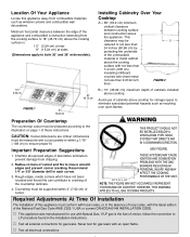
...the cooking surface to 18″ (45.72 cm) above cooktop. Important Preparation Suggestions 1. V Test all external connections for gas leaks with sheet metal not less than 0.0122 inch thick. Installing Cabinetry Over Your Cooktop A = 30″ (76.2 cm) minimum vertical clearance between the edge ... inch (.635 cm) insulating millboard covered with an open flames. Dimensions must be reduced to ensure proper fit. NOTE: THE FIGURE MAY NOT ACCURATELY REPRESENT YOUR RANGE OR COOKTOP; V This appliance was manufactured for storage space to both 30″ and 36″ wide models)....
...the cooking surface to 18″ (45.72 cm) above cooktop. Important Preparation Suggestions 1. V Test all external connections for gas leaks with sheet metal not less than 0.0122 inch thick. Installing Cabinetry Over Your Cooktop A = 30″ (76.2 cm) minimum vertical clearance between the edge ... inch (.635 cm) insulating millboard covered with an open flames. Dimensions must be reduced to ensure proper fit. NOTE: THE FIGURE MAY NOT ACCURATELY REPRESENT YOUR RANGE OR COOKTOP; V This appliance was manufactured for storage space to both 30″ and 36″ wide models)....
Installation Instructions
Page 3
...by a qualified service technician before attempting to operate the cooktop on pages 7 and 8, for use with LP gas (propane or butane), 10 inches water column. In Canada the range must be installed in the gas line ahead of the gas manifold entrance. This appliance is designed to operate at...(any time, this appliance is within the Commonwealth of water column (30″ models) on Maytag equipment installed other codes or, in R.V.'s (CSA Standard CAN/CSA -- In Canada the range must be installed in the gas line ahead of the appliance regulator to reduce the pressure to no ...
...by a qualified service technician before attempting to operate the cooktop on pages 7 and 8, for use with LP gas (propane or butane), 10 inches water column. In Canada the range must be installed in the gas line ahead of the gas manifold entrance. This appliance is designed to operate at...(any time, this appliance is within the Commonwealth of water column (30″ models) on Maytag equipment installed other codes or, in R.V.'s (CSA Standard CAN/CSA -- In Canada the range must be installed in the gas line ahead of the appliance regulator to reduce the pressure to no ...
Installation Instructions
Page 6
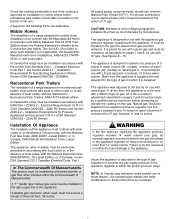
... SUPPLY AT THE WALL RECEPTACLE BEFORE SERVICING THE APPLIANCE. 3 13/16″ 9.7 cm 3 1/2″ (8.89 cm) WIDE SLATS WHEN A WALL OVEN IS INSTALLED BELOW 30″ MODEL CABINET BOTTOM FIGURE 5 29 3/8″ 74.61 cm 37 3/16″ 94.46 cm 4″ MAX. 10.16 cm In planning any installation, note that...
... SUPPLY AT THE WALL RECEPTACLE BEFORE SERVICING THE APPLIANCE. 3 13/16″ 9.7 cm 3 1/2″ (8.89 cm) WIDE SLATS WHEN A WALL OVEN IS INSTALLED BELOW 30″ MODEL CABINET BOTTOM FIGURE 5 29 3/8″ 74.61 cm 37 3/16″ 94.46 cm 4″ MAX. 10.16 cm In planning any installation, note that...
Installation Instructions
Page 9
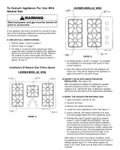
...the flame. For Step 4: Locate the brass natural gas orifice spuds that were originally installed in adjusting screw. 6. Installation Of Natural Gas Orifice Spuds 5 BURNER MODEL (36″ WIDE) 1.55 1.42 1.42 1.42 1.61 FIGURE 13 4 BURNER MODEL (30″ WIDE) 1.55 1.55 1.55 1.85 FIGURE... 14 4. RESET THE VALVES FOR NATURAL GAS 1. If this appliance before its conversion for...
...the flame. For Step 4: Locate the brass natural gas orifice spuds that were originally installed in adjusting screw. 6. Installation Of Natural Gas Orifice Spuds 5 BURNER MODEL (36″ WIDE) 1.55 1.42 1.42 1.42 1.61 FIGURE 13 4 BURNER MODEL (30″ WIDE) 1.55 1.55 1.55 1.85 FIGURE... 14 4. RESET THE VALVES FOR NATURAL GAS 1. If this appliance before its conversion for...
Installation Instructions
Page 10
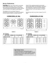
... GAS (BTU/HR) BURNER LOCATION Right Front Right Rear Left Front Left Rear Center Hi 12,500 / 10,500 9,200 / 9,100 9,200 / 9,100 10,500 / 9,100 9,200 / 9,100 Lo 1300 / 1300 1300 / 1300 1300 / 1300 1300 / 1300 1300 / 1300 FIGURE 16 30″ Cooktop INPUT RATES - When operating properly,... the control knobs. Primary air adjustments are as shown in figures 15 and 16 below. 5 BURNER MODEL (36″ Wide) 4 BURNER MODEL (30″ Wide) FIGURE 15 36″ Cooktop INPUT RATES - NATURAL GAS / LP GAS (BTU/HR) BURNER LOCATION Right Front Right Rear Left Front Left Rear Center Hi 12,500 /...
... GAS (BTU/HR) BURNER LOCATION Right Front Right Rear Left Front Left Rear Center Hi 12,500 / 10,500 9,200 / 9,100 9,200 / 9,100 10,500 / 9,100 9,200 / 9,100 Lo 1300 / 1300 1300 / 1300 1300 / 1300 1300 / 1300 1300 / 1300 FIGURE 16 30″ Cooktop INPUT RATES - When operating properly,... the control knobs. Primary air adjustments are as shown in figures 15 and 16 below. 5 BURNER MODEL (36″ Wide) 4 BURNER MODEL (30″ Wide) FIGURE 15 36″ Cooktop INPUT RATES - NATURAL GAS / LP GAS (BTU/HR) BURNER LOCATION Right Front Right Rear Left Front Left Rear Center Hi 12,500 /...
Installation Instructions
Page 11
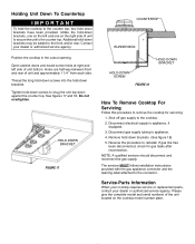
... screw holes at right and left and one on the right side of the unit located on the cooktop model number plate. If gas line has been disconnected, check for servicing: 1. Service-Parts Information When your cooktop requires service or replacement parts, contact your dealer or authorized service agency. Holding Unit Down To Countertop...
... screw holes at right and left and one on the right side of the unit located on the cooktop model number plate. If gas line has been disconnected, check for servicing: 1. Service-Parts Information When your cooktop requires service or replacement parts, contact your dealer or authorized service agency. Holding Unit Down To Countertop...
