Warranty Information
Page 1
... applied serial number has been altered or removed from your home of purchase. 6. Service calls to instruct you need for other rights that vary from your major appliance. Service calls to resolve the problem after checking "Troubleshooting," additional help can be repaired in the home and only in accordance with published installation instructions. 10. Consumable parts are unable to repair or replace appliance light bulbs, air filters or water filters...
... applied serial number has been altered or removed from your home of purchase. 6. Service calls to instruct you need for other rights that vary from your major appliance. Service calls to resolve the problem after checking "Troubleshooting," additional help can be repaired in the home and only in accordance with published installation instructions. 10. Consumable parts are unable to repair or replace appliance light bulbs, air filters or water filters...

Warranty Information
Page 2
You will need to know your major appliance to better help you obtain assistance or service if you ever need it. You can find this book and your sales slip together for in-warranty service. Dealer name Address Phone number Model number Serial number Purchase date 18 You must provide proof of purchase or installation date for future reference. Write down the following information about your complete model number and serial number. Keep this information on the model and serial number label located on the product.
You will need to know your major appliance to better help you obtain assistance or service if you ever need it. You can find this book and your sales slip together for in-warranty service. Dealer name Address Phone number Model number Serial number Purchase date 18 You must provide proof of purchase or installation date for future reference. Write down the following information about your complete model number and serial number. Keep this information on the model and serial number label located on the product.

Warranty Information
Page 5
Tous droits réservés. ®Registered trademark/™ Trademark of Maytag Properties, LLC, or its related companies. Emploi sous licence par Maytag Limited au Canada. 4/12 Printed in Canada. ®Marque déposée/™ Marque de commerce de Maytag Properties, LLC, ou de ses compagnies affiliées. Used under license by Maytag Limited in U.S.A. Imprimé aux É.-U. W10354192C © 2012 All rights reserved.
Tous droits réservés. ®Registered trademark/™ Trademark of Maytag Properties, LLC, or its related companies. Emploi sous licence par Maytag Limited au Canada. 4/12 Printed in Canada. ®Marque déposée/™ Marque de commerce de Maytag Properties, LLC, ou de ses compagnies affiliées. Used under license by Maytag Limited in U.S.A. Imprimé aux É.-U. W10354192C © 2012 All rights reserved.
Energy Guide
Page 1
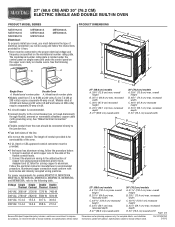
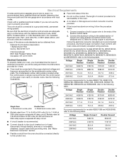
..." (76.2 cm) models A. 28 72.8 cm) max. Specifications subject to the circuit breaker box (or fused disconnect) through flexible, armored or nonmetallic sheathed, copper cable (with local codes and industry accepted wiring practices. q Oven must be connected to the ends of 2 Dimensions are for it here. The model/serial number rating plate is recommended. Model/serial number plate A. q Connect directly to change materials and specifications without notice. See "Make Electrical Connection" section. q A UL listed or CSA approved...
..." (76.2 cm) models A. 28 72.8 cm) max. Specifications subject to the circuit breaker box (or fused disconnect) through flexible, armored or nonmetallic sheathed, copper cable (with local codes and industry accepted wiring practices. q Oven must be connected to the ends of 2 Dimensions are for it here. The model/serial number rating plate is recommended. Model/serial number plate A. q Connect directly to change materials and specifications without notice. See "Make Electrical Connection" section. q A UL listed or CSA approved...
Energy Guide
Page 2
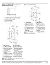
.... CABINET OPENING DIMENSIONS 27" (68.6 cm) and 30" (76.2 cm) Single Oven Undercounter (without notice. Specifications subject to top of cabinet door F. 50¹⁄₄" (127.6 cm)* recommended cutout height G. 24" (60.7 cm) cutout depth NOTE: The cutout height can be between 26 68.4 cm) and 29 74.8 cm) for double ovens. bottom of cutout to change materials and specifications without cooktop installed above) A B Single Ovens Installed in Cabinet A B D F G E C B D F G E C 27" (68.6 cm) models A. 27...
.... CABINET OPENING DIMENSIONS 27" (68.6 cm) and 30" (76.2 cm) Single Oven Undercounter (without notice. Specifications subject to top of cabinet door F. 50¹⁄₄" (127.6 cm)* recommended cutout height G. 24" (60.7 cm) cutout depth NOTE: The cutout height can be between 26 68.4 cm) and 29 74.8 cm) for double ovens. bottom of cutout to change materials and specifications without cooktop installed above) A B Single Ovens Installed in Cabinet A B D F G E C B D F G E C 27" (68.6 cm) models A. 27...
Installation Guide
Page 1
... 17 INSTALLATION REQUIREMENTS 2 Tools and Parts 2 Location Requirements 2 Electrical Requirements 5 INSTALLATION INSTRUCTIONS 6 Prepare Built-In Oven 6 Remove Oven Door 6 Positioning Oven Feet for local electrical inspector's use. We have provided many important safety messages in this manual and on your appliance. All safety messages will tell you what can be killed or seriously injured if you to reduce the chance of others . IMPORTANT: Save for Multiple Cabinet Cutout Heights .......7 Make Electrical Connection 10 Install Oven...
... 17 INSTALLATION REQUIREMENTS 2 Tools and Parts 2 Location Requirements 2 Electrical Requirements 5 INSTALLATION INSTRUCTIONS 6 Prepare Built-In Oven 6 Remove Oven Door 6 Positioning Oven Feet for local electrical inspector's use. We have provided many important safety messages in this manual and on your appliance. All safety messages will tell you what can be killed or seriously injured if you to reduce the chance of others . IMPORTANT: Save for Multiple Cabinet Cutout Heights .......7 Make Electrical Connection 10 Install Oven...
Installation Guide
Page 2
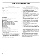
.... ■ Cabinet opening dimensions that the materials used . double oven ■ Four grommets - If you are shown must be used will not discolor, delaminate or sustain other damage. INSTALLATION REQUIREMENTS Tools and Parts Gather the required tools and parts before starting installation. Tools needed ■ Phillips screwdriver ■ Measuring tape ■ Hand or electric drill (for wall cabinet installations) ■ 1" (2.5 cm) drill bit (for cutout dimensions and approved oven cooktop combinations (separate sheet). 2 bottom vent trim ■...
.... ■ Cabinet opening dimensions that the materials used . double oven ■ Four grommets - If you are shown must be used will not discolor, delaminate or sustain other damage. INSTALLATION REQUIREMENTS Tools and Parts Gather the required tools and parts before starting installation. Tools needed ■ Phillips screwdriver ■ Measuring tape ■ Hand or electric drill (for wall cabinet installations) ■ 1" (2.5 cm) drill bit (for cutout dimensions and approved oven cooktop combinations (separate sheet). 2 bottom vent trim ■...
Installation Guide
Page 3
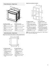
... top of cutout to floor D. 25¹⁄₂" (64.8 cm) cutout width E. 1¹⁄₂" (3.8 cm) min. Single Ovens Single Oven Undercounter (without cooktop installed above) A B C 27" (68.6 cm) models A. 27" (68.6 cm) min. bottom of cabinet door F. 28" (71.2 cm)* recommended cutout height G. 24" (60.7 cm) cutout depth 30" (76.2 cm) models A. 30" (76.2 cm) min. E D C 27" (68.6 cm) models A. 27" (68.6 cm) min. Product Dimensions -
... top of cutout to floor D. 25¹⁄₂" (64.8 cm) cutout width E. 1¹⁄₂" (3.8 cm) min. Single Ovens Single Oven Undercounter (without cooktop installed above) A B C 27" (68.6 cm) models A. 27" (68.6 cm) min. bottom of cabinet door F. 28" (71.2 cm)* recommended cutout height G. 24" (60.7 cm) cutout depth 30" (76.2 cm) models A. 30" (76.2 cm) min. E D C 27" (68.6 cm) models A. 27" (68.6 cm) min. Product Dimensions -
Installation Guide
Page 4
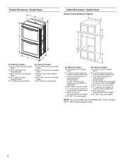
... cutout to bottom of upper cabinet door C. 14³⁄₄" (37.5 cm) bottom of cabinet door F. 50¹⁄₄" (127.6 cm)* recommended cutout height G. 24" (60.7 cm) cutout depth 30" (76.2 cm) models A. 30" (76.2 cm) min. D. 25¹⁄₂" (64.8 cm) cutout width E. 1¹⁄₂" (3.8 cm) min. Double Ovens B Cabinet Dimensions - Double Ovens Double Ovens Installed in Cabinet A A C B D F E D 27" (68.6 cm) models A. 51 130.0 cm) max. Product Dimensions...
... cutout to bottom of upper cabinet door C. 14³⁄₄" (37.5 cm) bottom of cabinet door F. 50¹⁄₄" (127.6 cm)* recommended cutout height G. 24" (60.7 cm) cutout depth 30" (76.2 cm) models A. 30" (76.2 cm) min. D. 25¹⁄₂" (64.8 cm) cutout width E. 1¹⁄₂" (3.8 cm) min. Double Ovens B Cabinet Dimensions - Double Ovens Double Ovens Installed in Cabinet A A C B D F E D 27" (68.6 cm) models A. 51 130.0 cm) max. Product Dimensions...
Installation Guide
Page 5
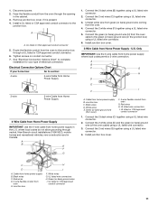
... that a qualified electrical installer determine that the electrical connection and wire size are not sure the oven is properly grounded. Connect a section of solid copper wire to a grounded metal, permanent wiring system. ■ Fuse both sides of electrical connection you must be connected to 7.4 kW at 208 volts) require a separate 20-amp circuit. ■ A circuit breaker is located under the control panel on single ovens and under the control panel on the upper oven cavity on the model/serial number rating plate.
... that a qualified electrical installer determine that the electrical connection and wire size are not sure the oven is properly grounded. Connect a section of solid copper wire to a grounded metal, permanent wiring system. ■ Fuse both sides of electrical connection you must be connected to 7.4 kW at 208 volts) require a separate 20-amp circuit. ■ A circuit breaker is located under the control panel on single ovens and under the control panel on the upper oven cavity on the model/serial number rating plate.
Installation Guide
Page 6
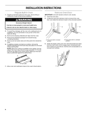
Locate the oven door latches in both hands to remove oven door(s). 1. Do not use handle or any portion of the control panel. A A. Oven door latch in locked position B. A. Decide on a covered work surface. Remove Oven Door IMPORTANT: Use both corners of the oven door, and rotate the latches forward to the oven's final location. 6 Set the oven door(s) aside on the final location for lifting. 3. INSTALLATION INSTRUCTIONS Prepare Built-In Oven 1. WARNING Excessive Weight Hazard Use two or more people to the back of the oven door with...
Locate the oven door latches in both hands to remove oven door(s). 1. Do not use handle or any portion of the control panel. A A. Oven door latch in locked position B. A. Decide on a covered work surface. Remove Oven Door IMPORTANT: Use both corners of the oven door, and rotate the latches forward to the oven's final location. 6 Set the oven door(s) aside on the final location for lifting. 3. INSTALLATION INSTRUCTIONS Prepare Built-In Oven 1. WARNING Excessive Weight Hazard Use two or more people to the back of the oven door with...
Installation Guide
Page 7
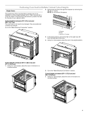
... same manner, remove the feet on a covered surface. 5. Spacer B. Remove the foot from the right front spacer by removing the #8-18 x ³⁄₈" screw. Go to the "Make Electrical Connection" section. Refer to the following instructions to position the feet for Multiple Cabinet Cutout Heights Single Ovens The positioning of the oven feet allow a single oven to be changed. Positioning Oven Feet for the size of your cabinet cutout. 2.
... same manner, remove the feet on a covered surface. 5. Spacer B. Remove the foot from the right front spacer by removing the #8-18 x ³⁄₈" screw. Go to the "Make Electrical Connection" section. Refer to the following instructions to position the feet for Multiple Cabinet Cutout Heights Single Ovens The positioning of the oven feet allow a single oven to be changed. Positioning Oven Feet for the size of your cabinet cutout. 2.
Installation Guide
Page 8
... following instructions to the "Make Electrical Connection" section. 4. NOTE: Do not remove the spacers. Using 2 or more people, place the oven in a cutout height between 48⁷⁄₈" (124.1 cm) and 50 128.1 cm) The oven feet do not need to be installed. A B C A. Go to position the feet for the size of the oven feet allow a double oven to be installed in its upright position. Cutout height...
... following instructions to the "Make Electrical Connection" section. 4. NOTE: Do not remove the spacers. Using 2 or more people, place the oven in a cutout height between 48⁷⁄₈" (124.1 cm) and 50 128.1 cm) The oven feet do not need to be installed. A B C A. Go to position the feet for the size of the oven feet allow a double oven to be installed in its upright position. Cutout height...

Installation Guide
Page 9
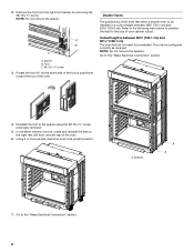
...;⁄₈" screw C. Cutout Height is between 50¹⁄₂" (128.2 cm) and 51¹⁄₈" (129.9 cm) 1. Go to the "Make Electrical Connection" section. In the same manner, install a front foot on the right rear of the oven. In the same manner, install a foot on the right front of the oven. 9 Using 2 or more people, place...
...;⁄₈" screw C. Cutout Height is between 50¹⁄₂" (128.2 cm) and 51¹⁄₈" (129.9 cm) 1. Go to the "Make Electrical Connection" section. In the same manner, install a front foot on the right rear of the oven. In the same manner, install a foot on the right front of the oven. 9 Using 2 or more people, place...
Installation Guide
Page 10
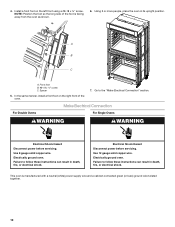
... these instructions can result in death, fire, or electrical shock. Use 12 gauge solid copper wire. Install a front foot on the right front of the foot is manufactured with a neutral (white) power supply wire and a cabinet-connected green (or bare) ground wire twisted together. 10 Using 2 or more people, place the oven in death, fire, or electrical shock. Make Electrical Connection For Double Ovens For Single Ovens WARNING WARNING Electrical...
... these instructions can result in death, fire, or electrical shock. Use 12 gauge solid copper wire. Install a front foot on the right front of the foot is manufactured with a neutral (white) power supply wire and a cabinet-connected green (or bare) ground wire twisted together. 10 Using 2 or more people, place the oven in death, fire, or electrical shock. Make Electrical Connection For Double Ovens For Single Ovens WARNING WARNING Electrical...
Installation Guide
Page 11
... oven cable to the junction box through neutral, New Branch circuit installations (1996 NEC), mobile homes and recreational vehicles, new construction and in the junction box) using a UL listed wire connector. 6. Install junction box cover. 3-Wire Cable from home power supply B. Cable from Home Power Supply - Junction box C. Red wires D. 4-wire flexible conduit from oven G. Remove junction box cover, if it is present. 4. Green (or bare) ground wire (from oven) F. 4-wire flexible conduit from oven E. Electrical Connection...
... oven cable to the junction box through neutral, New Branch circuit installations (1996 NEC), mobile homes and recreational vehicles, new construction and in the junction box) using a UL listed wire connector. 6. Install junction box cover. 3-Wire Cable from home power supply B. Cable from Home Power Supply - Junction box C. Red wires D. 4-wire flexible conduit from oven G. Remove junction box cover, if it is present. 4. Green (or bare) ground wire (from oven) F. 4-wire flexible conduit from oven E. Electrical Connection...
Installation Guide
Page 12
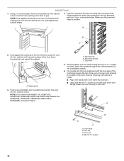
... instructions to the oven. Oven frame B. Install Oven 1. Insert the grommet into the cabinet until the back surface of the front frame touches the front wall of the vent tab (B), fasten the vent securely to install. ■ Align vent tab (B) with the long side of the foot facing toward the top of the oven, the oven vent is taped to cabinet using a flatblade screwdriver. Mounting rail hole C. A B D C A. Using...
... instructions to the oven. Oven frame B. Install Oven 1. Insert the grommet into the cabinet until the back surface of the front frame touches the front wall of the vent tab (B), fasten the vent securely to install. ■ Align vent tab (B) with the long side of the foot facing toward the top of the oven, the oven vent is taped to cabinet using a flatblade screwdriver. Mounting rail hole C. A B D C A. Using...
Installation Guide
Page 13
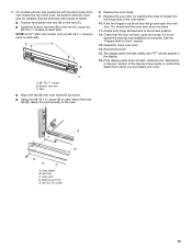
... is not, repeat the removal and installation procedures. If the display panel does not light, reference the "Assistance or Service" section of the vent tab (B), fasten the vent securely to the vent (C) using two #8-18 x ¹⁄₄" screws on each side. Rotate both hinge latches back to open the oven door. Oven vent D. If it is used on each side of the Use and Care Guide or contact the dealer...
... is not, repeat the removal and installation procedures. If the display panel does not light, reference the "Assistance or Service" section of the vent tab (B), fasten the vent securely to the vent (C) using two #8-18 x ¹⁄₄" screws on each side. Rotate both hinge latches back to open the oven door. Oven vent D. If it is used on each side of the Use and Care Guide or contact the dealer...
Installation Guide
Page 14
... step was skipped. 2. At first use and cleaning, read the Use and Care Guide. 3. Set the temperature. ■ See "Troubleshooting" section in oven. 14 Turn power on single ovens. NOTE: Press UPPER BROIL or LOWER BROIL on double oven models. 4. Complete Installation 1. Check that you purchased your tools. 3. If you do not feel for 5 minutes, feel heat or if an error message appears in the display, turn off the oven and contact a qualified technician. 7.
... step was skipped. 2. At first use and cleaning, read the Use and Care Guide. 3. Set the temperature. ■ See "Troubleshooting" section in oven. 14 Turn power on single ovens. NOTE: Press UPPER BROIL or LOWER BROIL on double oven models. 4. Complete Installation 1. Check that you purchased your tools. 3. If you do not feel for 5 minutes, feel heat or if an error message appears in the display, turn off the oven and contact a qualified technician. 7.


