

Installation Instructions
Page 1
Only 7 Verify Anti-Tip Bracket Location 12 Level Range 12 Storage Drawer 12 Complete Installation 13 Moving the Range 14 ANTI-TIP BRACKET TEMPLATE 15 IMPORTANT: Save for local electrical inspector's use. Only 4 INSTALLATION INSTRUCTIONS 6 Unpack Range 6 Install Anti-Tip Bracket 6 Electrical Connection - U.S.A. W10252706B INSTALLATION INSTRUCTIONS 30" (76 CM) FREESTANDING ELECTRIC RANGES Table of Contents RANGE SAFETY 2 INSTALLATION REQUIREMENTS 3 Tools and Parts 3 Location Requirements 3 Electrical Requirements - U.S.A.
Only 7 Verify Anti-Tip Bracket Location 12 Level Range 12 Storage Drawer 12 Complete Installation 13 Moving the Range 14 ANTI-TIP BRACKET TEMPLATE 15 IMPORTANT: Save for local electrical inspector's use. Only 4 INSTALLATION INSTRUCTIONS 6 Unpack Range 6 Install Anti-Tip Bracket 6 Electrical Connection - U.S.A. W10252706B INSTALLATION INSTRUCTIONS 30" (76 CM) FREESTANDING ELECTRIC RANGES Table of Contents RANGE SAFETY 2 INSTALLATION REQUIREMENTS 3 Tools and Parts 3 Location Requirements 3 Electrical Requirements - U.S.A.
Installation Instructions
Page 3
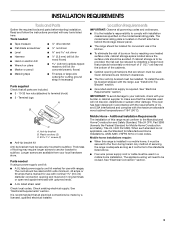
...to comply with installation clearances specified on the left side frame behind the storage drawer panel. ■ The range should be reduced by a licensed, qualified electrical installer. INSTALLATION REQUIREMENTS Tools and Parts Gather the required tools and parts before starting installation. Terminal lugs A ...;" nut driver and nut driver 3.2 mm) drill bit (for wood floors) 4.8 mm) carbide-tipped masonry drill bit (for concrete/ceramic floors) ■ Tin snips or large wire cutters (for cutting ground strap if necessary) Parts supplied Check that all governing codes and...
...to comply with installation clearances specified on the left side frame behind the storage drawer panel. ■ The range should be reduced by a licensed, qualified electrical installer. INSTALLATION REQUIREMENTS Tools and Parts Gather the required tools and parts before starting installation. Terminal lugs A ...;" nut driver and nut driver 3.2 mm) drill bit (for wood floors) 4.8 mm) carbide-tipped masonry drill bit (for concrete/ceramic floors) ■ Tin snips or large wire cutters (for cutting ground strap if necessary) Parts supplied Check that all governing codes and...
Installation Instructions
Page 4
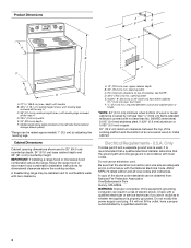
... use an extension cord. Check with zero clearance. Product Dimensions A C B A F B C D E F E D A. 27 69.9 cm) max. IMPORTANT: If installing a range hood or microwave hood combination above code standards can be installed next to 22" (55.9 cm) from floor F 2.2 cm) min. D. 30¹⁄₈" (76... ground path and wire gauge are adequate and in conformance with the National Electrical Code, ANSI/ NFPA 70-latest edition and all the way in accordance with not less than No. 28 MSG sheet steel, 0.015" (0.4 mm) stainless steel, 0.024" (0.6 mm) aluminum or 0.020" (0.5 mm) copper...
... use an extension cord. Check with zero clearance. Product Dimensions A C B A F B C D E F E D A. 27 69.9 cm) max. IMPORTANT: If installing a range hood or microwave hood combination above code standards can be installed next to 22" (55.9 cm) from floor F 2.2 cm) min. D. 30¹⁄₈" (76... ground path and wire gauge are adequate and in conformance with the National Electrical Code, ANSI/ NFPA 70-latest edition and all the way in accordance with not less than No. 28 MSG sheet steel, 0.015" (0.4 mm) stainless steel, 0.024" (0.6 mm) aluminum or 0.020" (0.5 mm) copper...
Installation Instructions
Page 5
...power supply cord rated at the junction box). ■ Wire sizes and connections must conform with the rating of the range. ■ The wiring diagram is located on the back of electrical connection you must be identified by a green or green/yellow cover and the neutral conductor by a link. If ...than the total connected load listed on the appliance end must be at the point the power supply cord enters the appliance. See "Electrical Connection." or 50-amp range power supply cord (pigtail). This cord contains 4 copper conductors with ring terminals or open -end spade terminals with...
...power supply cord rated at the junction box). ■ Wire sizes and connections must conform with the rating of the range. ■ The wiring diagram is located on the back of electrical connection you must be identified by a green or green/yellow cover and the neutral conductor by a link. If ...than the total connected load listed on the appliance end must be at the point the power supply cord enters the appliance. See "Electrical Connection." or 50-amp range power supply cord (pigtail). This cord contains 4 copper conductors with ring terminals or open -end spade terminals with...

Installation Instructions
Page 7
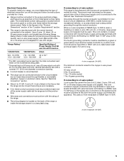
... 40 amp power supply cord. Plug into holes with screws provided. Disconnect power. 2. Terminal block cover C. Electrical Connection - Electrical Shock Hazard Disconnect power before servicing. Electrically ground range. Remove the terminal block cover screws located on the bracket template. A B C A. Depending on the bracket... outlet. Hex-head screws 7 5. Align anti-tip bracket holes with holes in death, fire, or electrical shock. 1. To mount anti-tip bracket to concrete or ceramic floor, use a 4.8 mm) masonry drill bit to wood floor, drill two ¹⁄₈" ...
... 40 amp power supply cord. Plug into holes with screws provided. Disconnect power. 2. Terminal block cover C. Electrical Connection - Electrical Shock Hazard Disconnect power before servicing. Electrically ground range. Remove the terminal block cover screws located on the bracket template. A B C A. Depending on the bracket... outlet. Hex-head screws 7 5. Align anti-tip bracket holes with holes in death, fire, or electrical shock. 1. To mount anti-tip bracket to concrete or ceramic floor, use a 4.8 mm) masonry drill bit to wood floor, drill two ¹⁄₈" ...

Installation Instructions
Page 8
...or fused Direct wire disconnect 5" (12.7 cm) 3-wire receptacle (NEMA type 10-50R) A UL listed, 250-volt minimum, 40-amp, range power supply cord 3-wire connection: Power supply cord Style 2: Direct wire strain relief ■ Remove the knockout as needed for your home has: ... supply cord 4-wire connection: Power supply cord A A. Save the ground-link screw and the end of the range. Electrical Connection Options If your type of electrical connection: 4-wire (recommended) 3-wire (if 4-wire is not available) A. Add strain relief. Removable retaining nut B. Complete installation ...
...or fused Direct wire disconnect 5" (12.7 cm) 3-wire receptacle (NEMA type 10-50R) A UL listed, 250-volt minimum, 40-amp, range power supply cord 3-wire connection: Power supply cord Style 2: Direct wire strain relief ■ Remove the knockout as needed for your home has: ... supply cord 4-wire connection: Power supply cord A A. Save the ground-link screw and the end of the range. Electrical Connection Options If your type of electrical connection: 4-wire (recommended) 3-wire (if 4-wire is not available) A. Add strain relief. Removable retaining nut B. Complete installation ...

Installation Instructions
Page 10
... directly to the terminal block. Line 2 (red) wire D. Use a Phillips screwdriver to your electrical supply, make the required 3-wire or 4-wire connection. 1. Pull the wires through bottom of the range. Line 1 (black) wire 4. Terminal lug B. Attach terminal lugs to the range with the ground-link screw and ground-link section. C D E A. Strip the insulation...
... directly to the terminal block. Line 2 (red) wire D. Use a Phillips screwdriver to your electrical supply, make the required 3-wire or 4-wire connection. 1. Pull the wires through bottom of the range. Line 1 (black) wire 4. Terminal lug B. Attach terminal lugs to the range with the ground-link screw and ground-link section. C D E A. Strip the insulation...
Installation Instructions
Page 13
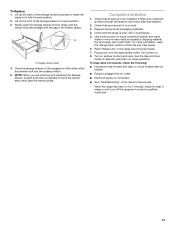
...7. Plug power cord into an outlet. ■ Electrical supply is level. If range is intact and tight; Complete Installation 1. Turn power on both sides, slide the drawer back into the range until the drawer side rails engage with a soft cloth. If range does not operate, check the following: ■ ... for specific instruction on surface burners and oven. To Replace: 1. Lift up the front of the storage drawer and place it inside the range in the Use and Care Guide. Slowly push the storage drawer into the closed position. 5. NOTE: When you have all of /recycle all...
...7. Plug power cord into an outlet. ■ Electrical supply is level. If range is intact and tight; Complete Installation 1. Turn power on both sides, slide the drawer back into the range until the drawer side rails engage with a soft cloth. If range does not operate, check the following: ■ ... for specific instruction on surface burners and oven. To Replace: 1. Lift up the front of the storage drawer and place it inside the range in the Use and Care Guide. Slowly push the storage drawer into the closed position. 5. NOTE: When you have all of /recycle all...
Installation Instructions
Page 14
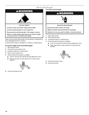
...the anti-tip bracket securely attached to rear range foot. Check that range is level. 6. Electrical Shock Hazard Disconnect power before operating. Check that anti-tip bracket is under anti-tip bracket. 5. Check that range is level. 14 Replace all parts and panels... before servicing. Check that anti-tip bracket is under anti-tip bracket. Slide range forward. 2. Complete cleaning or maintenance. 4. Plug in death or electrical shock. 1. Failure to avoid damaging the floor covering. Disconnect power. 2. Complete cleaning or maintenance....
...the anti-tip bracket securely attached to rear range foot. Check that range is level. 6. Electrical Shock Hazard Disconnect power before operating. Check that anti-tip bracket is under anti-tip bracket. 5. Check that range is level. 14 Replace all parts and panels... before servicing. Check that anti-tip bracket is under anti-tip bracket. Slide range forward. 2. Complete cleaning or maintenance. 4. Plug in death or electrical shock. 1. Failure to avoid damaging the floor covering. Disconnect power. 2. Complete cleaning or maintenance....

Owners Manual
Page 3
...Children should never be careful to the sudden change in Place - Only certain types of glass, glass/ceramic, ceramic, earthenware, or other flammable materials contact heating elements or interior surfaces of electric shock, or fire. ■ Glazed Cooking Utensils - Heating elements should not be taken not to ... , do not let potholder contact hot heating element in color. Other surfaces of the appliance may result in cabinets above a range or on the range to cause burns - Surface units may penetrate the broken cooktop and create a risk of clothing. Do not use dry chemical or...
...Children should never be careful to the sudden change in Place - Only certain types of glass, glass/ceramic, ceramic, earthenware, or other flammable materials contact heating elements or interior surfaces of electric shock, or fire. ■ Glazed Cooking Utensils - Heating elements should not be taken not to ... , do not let potholder contact hot heating element in color. Other surfaces of the appliance may result in cabinets above a range or on the range to cause burns - Surface units may penetrate the broken cooktop and create a risk of clothing. Do not use dry chemical or...


