Installation Instructions
Page 2
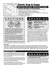
... ALL INSTALLATION INSTRUCTIONS. CONNECTING THE RANGE The range must still observe the safety precautions as stated in the USE and CARE MANUAL and avoid using range. • Improper installation, adjustment, alteration, service, maintenance or use of the ANTI-TIP device minimizes the risk of TIP-OVER. Your local utility company will tell you whether the present electric service to your home is not obstructed below the range. requires a single phase three wire...
... ALL INSTALLATION INSTRUCTIONS. CONNECTING THE RANGE The range must still observe the safety precautions as stated in the USE and CARE MANUAL and avoid using range. • Improper installation, adjustment, alteration, service, maintenance or use of the ANTI-TIP device minimizes the risk of TIP-OVER. Your local utility company will tell you whether the present electric service to your home is not obstructed below the range. requires a single phase three wire...
Installation Instructions
Page 3
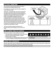
... disconnect the ground wire and connect to ground in this manual. Slide range forward to disengage range from accidentally tipping, range must be secured to local code. Please give the complete model and serial number of the conduit.) If used , use connectors recognized for power requirements. The neutral of this unit for joining aluminum to local electrical code and National Electrical Code. Disconnect electrical supply to the service neutral. Your range may not be...
... disconnect the ground wire and connect to ground in this manual. Slide range forward to disengage range from accidentally tipping, range must be secured to local code. Please give the complete model and serial number of the conduit.) If used , use connectors recognized for power requirements. The neutral of this unit for joining aluminum to local electrical code and National Electrical Code. Disconnect electrical supply to the service neutral. Your range may not be...
Installation Instructions
Page 8
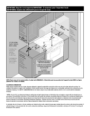
...inch (76.2 cm) dimension may be representative of burns or fire by installing a range hood that projects horizontally a minimum of 5 inches (13 cm) beyond the bottom of the elevated oven will specify the minimum acceptable dimension between cooking top and wall cabinet shown on the sides below the cooktop...National Fuel Gas Code or in mobile homes when they are protected with fireproof materials in accordance with the installation drawings. * NOTE: 30 inch (76.2 cm) dimension between the cooktop and elevated oven. For complete information in regard to not less than 24 inches (61...
...inch (76.2 cm) dimension may be representative of burns or fire by installing a range hood that projects horizontally a minimum of 5 inches (13 cm) beyond the bottom of the elevated oven will specify the minimum acceptable dimension between cooking top and wall cabinet shown on the sides below the cooktop...National Fuel Gas Code or in mobile homes when they are protected with fireproof materials in accordance with the installation drawings. * NOTE: 30 inch (76.2 cm) dimension between the cooktop and elevated oven. For complete information in regard to not less than 24 inches (61...
Parts List
Page 1
Model Number - Repair Parts List MODEL NUMBER MEP5775BAF RANGE When requesting service or ordering parts, always provide the following information: - Product Type - Part Description ©2005 Maytag Services Part Number -
Model Number - Repair Parts List MODEL NUMBER MEP5775BAF RANGE When requesting service or ordering parts, always provide the following information: - Product Type - Part Description ©2005 Maytag Services Part Number -
Parts List
Page 3
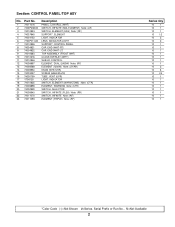
Part No. Section: CONTROL PANEL/TOP ASY No. Description 1 74011076 PANEL, CONTROL (WHT) 2 7403P238-60 SWITCH, INFINITE (SML ELEMENT) Note: (LR) 3 74010824 SWITCH, ELEMENT (LRG) Note: (RF) 4 74007845 SUPPORT, ELEMENT 5 74004153 LIGHT, INDICATOR 6 7730P011-60 LENS, INDICATOR LIGHT 7 74010826 8 74004821 SUPPORT, CONTROL PANEL CAP, END (WHT-RT) 8 74004822 9 74010663 10 74010676 11 74010846 12 74008897 13 74008568 CAP, END (WHT-LT) TOP ASSEMBLY (FROST WHT) CLOCK/OVERLAY (WHT) SHIELD, CONTROL ELEMENT, DUAL (2400W...
Part No. Section: CONTROL PANEL/TOP ASY No. Description 1 74011076 PANEL, CONTROL (WHT) 2 7403P238-60 SWITCH, INFINITE (SML ELEMENT) Note: (LR) 3 74010824 SWITCH, ELEMENT (LRG) Note: (RF) 4 74007845 SUPPORT, ELEMENT 5 74004153 LIGHT, INDICATOR 6 7730P011-60 LENS, INDICATOR LIGHT 7 74010826 8 74004821 SUPPORT, CONTROL PANEL CAP, END (WHT-RT) 8 74004822 9 74010663 10 74010676 11 74010846 12 74008897 13 74008568 CAP, END (WHT-LT) TOP ASSEMBLY (FROST WHT) CLOCK/OVERLAY (WHT) SHIELD, CONTROL ELEMENT, DUAL (2400W...
Parts List
Page 4
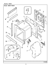
Section: BODY Model: MEP5775BAF C14-925 3
Section: BODY Model: MEP5775BAF C14-925 3
Parts List
Page 5
... 74008264 BRACKET, SWITCH ACTUATOR SCREW----NA SPRING, DOOR SWITCH ROD, DOOR LIGHT SWITCH BUMPER, ROD INSULATOR 14 74010819 15 74010820 LATCH ASY EXTENSION, HEAT SHEILD 16 74010822 16 74010821 17 74010823 18 74011206 19 74004180 20 74001338 - 74011202 21 74011200 PANEL, SHIELD (RT) PANEL, SHIELD (LT) FAN, COOLING FLEX CABLE ASSEMBLY BRACKET, POWER SUPPLY SHIELD, VENT (WHT) TRIM, SIDE (LT-WHT) TRIM, SIDE (RT-WHT) 22 74006096 COVER, WIRE (REAR...
... 74008264 BRACKET, SWITCH ACTUATOR SCREW----NA SPRING, DOOR SWITCH ROD, DOOR LIGHT SWITCH BUMPER, ROD INSULATOR 14 74010819 15 74010820 LATCH ASY EXTENSION, HEAT SHEILD 16 74010822 16 74010821 17 74010823 18 74011206 19 74004180 20 74001338 - 74011202 21 74011200 PANEL, SHIELD (RT) PANEL, SHIELD (LT) FAN, COOLING FLEX CABLE ASSEMBLY BRACKET, POWER SUPPLY SHIELD, VENT (WHT) TRIM, SIDE (LT-WHT) TRIM, SIDE (RT-WHT) 22 74006096 COVER, WIRE (REAR...
Parts List
Page 6
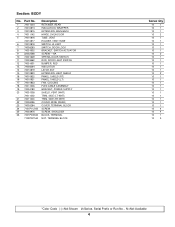
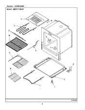
Section: OVEN/BASE Model: MEP5775BAF C12-553 5
Section: OVEN/BASE Model: MEP5775BAF C12-553 5
Parts List
Page 8
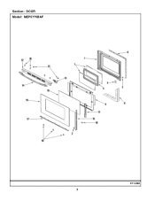
Section: DOOR Model: MEP5775BAF C11-882 7
Section: DOOR Model: MEP5775BAF C11-882 7
Parts List
Page 9
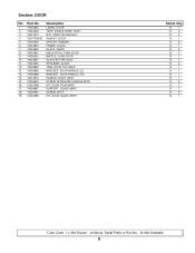
..., RUBBER 6 74003644 FRAME, GLASS 7 74003645 8 74003647 GLASS, INNER INSULATION, OVEN DOOR 9 74009502 10 74004857 11 74003650 12 74009690 13 74009699 13 74009698 BAFFLE, OVEN DOOR GLASS W/TAPE ASSY RETAINER, GLASS TRIM, DOOR TOP (WHT) BRACKET, DOOR HANDLE (LT) BRACKET, DOOR HANDLE (RT) 14 74010972 15 74006635 HANDLE, DOOR (WHT) SCREW W/WASHER (HANDLE MTG) 16 12002358 17 74009687 18 74009540 19 12002396 KIT, DOOR TRIM (WHT) SUPPORT, GLASS (WHT) SCREW (WHT) KIT, DOOR GLASS (WHT) Series Qty 10 1 10...
..., RUBBER 6 74003644 FRAME, GLASS 7 74003645 8 74003647 GLASS, INNER INSULATION, OVEN DOOR 9 74009502 10 74004857 11 74003650 12 74009690 13 74009699 13 74009698 BAFFLE, OVEN DOOR GLASS W/TAPE ASSY RETAINER, GLASS TRIM, DOOR TOP (WHT) BRACKET, DOOR HANDLE (LT) BRACKET, DOOR HANDLE (RT) 14 74010972 15 74006635 HANDLE, DOOR (WHT) SCREW W/WASHER (HANDLE MTG) 16 12002358 17 74009687 18 74009540 19 12002396 KIT, DOOR TRIM (WHT) SUPPORT, GLASS (WHT) SCREW (WHT) KIT, DOOR GLASS (WHT) Series Qty 10 1 10...
Parts List
Page 10
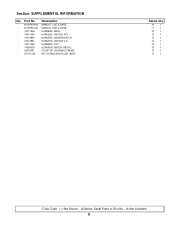
Description - 8113P500-60 MANUAL, USE & CARE - 8113P561-60 MANUAL, USE & CARE - 74011205 HARNESS, MAIN - 74011090 HARNESS, SWITCH (RT) - 74010849 HARNESS, SENSOR/LATCH - 74010851 HARNESS, SWITCH (LT) - 74011092 - 74006500 HARNESS, TOP SCRAPER, RAZOR (METAL) - 20000001 COOKTOP CLEANING CREME - K71FILLW KIT, EXTRUSION FILLER (WHT) Series Qty 10 1 11 1 10 1 10 1 10 1 10 1 10 1 10 1 10 1 10 1 *Color Code (-)=Not Shown #=Series, Serial Prefix or Run No., N=Not Available 9 Part No. Section: SUPPLEMENTAL INFORMATION No.
Description - 8113P500-60 MANUAL, USE & CARE - 8113P561-60 MANUAL, USE & CARE - 74011205 HARNESS, MAIN - 74011090 HARNESS, SWITCH (RT) - 74010849 HARNESS, SENSOR/LATCH - 74010851 HARNESS, SWITCH (LT) - 74011092 - 74006500 HARNESS, TOP SCRAPER, RAZOR (METAL) - 20000001 COOKTOP CLEANING CREME - K71FILLW KIT, EXTRUSION FILLER (WHT) Series Qty 10 1 11 1 10 1 10 1 10 1 10 1 10 1 10 1 10 1 10 1 *Color Code (-)=Not Shown #=Series, Serial Prefix or Run No., N=Not Available 9 Part No. Section: SUPPLEMENTAL INFORMATION No.
Parts List
Page 11
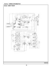
Section: WIRING INFORMATION Model: MEP5775BAF 15003732 10
Section: WIRING INFORMATION Model: MEP5775BAF 15003732 10
Dimensions
Page 1
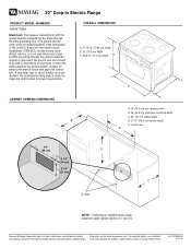
...-17-07 The model/serial rating plate is recommended. Connect all wires to the service neutral. Connect the white neutral to the branch circuit with product. OVERALL DIMENSIONS A. 27-15/16" (70.96 cm) Height B. 30" (76.2 cm) Width C. 28-5/16" (71.9 cm) Depth A B C CABINET OPENING DIMENSIONS B A. 30" (76.2 cm) min. A time-delay fuse or circuit breaker is under the range top control panel for planning purposes...
...-17-07 The model/serial rating plate is recommended. Connect all wires to the service neutral. Connect the white neutral to the branch circuit with product. OVERALL DIMENSIONS A. 27-15/16" (70.96 cm) Height B. 30" (76.2 cm) Width C. 28-5/16" (71.9 cm) Depth A B C CABINET OPENING DIMENSIONS B A. 30" (76.2 cm) min. A time-delay fuse or circuit breaker is under the range top control panel for planning purposes...


