
Use and Care Manual
Page 3
DRYER SAFETY Your safety and the safety of injury, and tell you what the potential hazard is the safety alert symbol. We have provided many important ...
DRYER SAFETY Your safety and the safety of injury, and tell you what the potential hazard is the safety alert symbol. We have provided many important ...

Use and Care Manual
Page 4
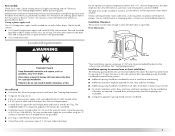
...9632; #2 Phillips screwdriver ■ Level ■ Adjustable wrench that opens to 1" (25 mm) or hex-head socket wrench (for adjusting dryer feet) ■ Wire stripper (direct wire installations) ■ Vent clamps ■ Caulking gun and compound (for grounding requirements. Short inlet hose... legs (4) B. Rubber washer 4 IMPORTANT SAFETY INSTRUCTIONS WARNING: To reduce the risk of fire, electric shock, or injury to persons when using the dryer, follow the instructions provided with right-angle connector E. SAVE THESE INSTRUCTIONS INSTALLATION INSTRUCTIONS Tools and Parts...
...9632; #2 Phillips screwdriver ■ Level ■ Adjustable wrench that opens to 1" (25 mm) or hex-head socket wrench (for adjusting dryer feet) ■ Wire stripper (direct wire installations) ■ Vent clamps ■ Caulking gun and compound (for grounding requirements. Short inlet hose... legs (4) B. Rubber washer 4 IMPORTANT SAFETY INSTRUCTIONS WARNING: To reduce the risk of fire, electric shock, or injury to persons when using the dryer, follow the instructions provided with right-angle connector E. SAVE THESE INSTRUCTIONS INSTALLATION INSTRUCTIONS Tools and Parts...
Use and Care Manual
Page 5
... 45ºF (7ºC). Check existing electrical supply and venting and see "Electrical Requirements" and "Venting Requirements" before purchasing parts. Location Requirements Do not operate your dryer. You may also contact the dealer from whom you purchased your dryer at least 4 ft (1.22 m) long... for use the water supply for your washer using a power supply cord, a grounded electrical outlet located within 4 ft (1.2 m) of the water fill valves, and water pressure of the dryer. Contact your dryer. Parts needed ) which are provided. ■ 20-100 psi (138-690 kPa)...
... 45ºF (7ºC). Check existing electrical supply and venting and see "Electrical Requirements" and "Venting Requirements" before purchasing parts. Location Requirements Do not operate your dryer. You may also contact the dealer from whom you purchased your dryer at least 4 ft (1.22 m) long... for use the water supply for your washer using a power supply cord, a grounded electrical outlet located within 4 ft (1.2 m) of the water fill valves, and water pressure of the dryer. Contact your dryer. Parts needed ) which are provided. ■ 20-100 psi (138-690 kPa)...
Use and Care Manual
Page 6
... mobile homes to the neutral wire, see "Optional 3-wire connection" in ring terminals or spade terminals with a 3-wire electrical supply connection. Only It is your dryer, you must be used when the appliance is installed in the neutral or grounding circuit. ■ Do not use with... is secured under the neutral terminal (center or white wire) of a neutral ground wire to introduce outside air into the dryer. The kit should be sure that the electrical connection is isolated from : National Fire Protection Association, One Batterymarch Park, Quincy, MA 02269. ■ To supply the ...
... mobile homes to the neutral wire, see "Optional 3-wire connection" in ring terminals or spade terminals with a 3-wire electrical supply connection. Only It is your dryer, you must be used when the appliance is installed in the neutral or grounding circuit. ■ Do not use with... is secured under the neutral terminal (center or white wire) of a neutral ground wire to introduce outside air into the dryer. The kit should be sure that the electrical connection is isolated from : National Fire Protection Association, One Batterymarch Park, Quincy, MA 02269. ■ To supply the ...
Use and Care Manual
Page 7
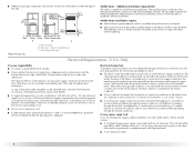
... can result in doubt as to the equipment-grounding terminal or lead on the power supply cord: if it will reduce the risk of electric shock by providing a path of malfunction or breakdown, grounding will not fit the outlet, have a proper outlet installed by a white cover...electric shock. If your outlet looks like this : 4-wire receptacle (14-30R) Then choose a 4-wire power supply cord with ring or spade terminals and UL listed strain relief. If connecting by direct wire: Power supply cable must be identified by a qualified electrician. Do not modify the plug on the dryer...
... can result in doubt as to the equipment-grounding terminal or lead on the power supply cord: if it will reduce the risk of electric shock by providing a path of malfunction or breakdown, grounding will not fit the outlet, have a proper outlet installed by a white cover...electric shock. If your outlet looks like this : 4-wire receptacle (14-30R) Then choose a 4-wire power supply cord with ring or spade terminals and UL listed strain relief. If connecting by direct wire: Power supply cable must be identified by a qualified electrician. Do not modify the plug on the dryer...

Use and Care Manual
Page 8
... adequate and in length. Connect to an individual branch circuit. ■ This dryer is within reach of electric shock. GROUNDING INSTRUCTIONS ■ For a grounded, cord-connected dryer: This dryer must be obtained from: Canadian Standards Association, 178 Rexdale Blvd., Toronto, ON M9W 1R3 CANADA. ■ To supply the required 4 wire, single phase, 120/240...
... adequate and in length. Connect to an individual branch circuit. ■ This dryer is within reach of electric shock. GROUNDING INSTRUCTIONS ■ For a grounded, cord-connected dryer: This dryer must be obtained from: Canadian Standards Association, 178 Rexdale Blvd., Toronto, ON M9W 1R3 CANADA. ■ To supply the required 4 wire, single phase, 120/240...
Use and Care Manual
Page 10
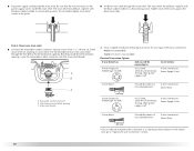
... type 10-30R) A fused disconnect or circuit breaker box* 4-wire connection: Direct Wire A UL listed, 120/240-volt minimum, 30-amp, dryer power supply cord* 3-wire connection: Power Supply Cord 3-wire direct A fused disconnect or circuit breaker box* 3-wire connection: Direct Wire (89 mm...connection of a cabinet-ground conductor to the neutral wire, go to "Optional 3-wire connection" section. 10 Put the threaded section of electrical connection: 4-wire (recommended) 3-wire (if 4-wire is inside the terminal block opening, screw the removable conduit connector onto the strain relief...
... type 10-30R) A fused disconnect or circuit breaker box* 4-wire connection: Direct Wire A UL listed, 120/240-volt minimum, 30-amp, dryer power supply cord* 3-wire connection: Power Supply Cord 3-wire direct A fused disconnect or circuit breaker box* 3-wire connection: Direct Wire (89 mm...connection of a cabinet-ground conductor to the neutral wire, go to "Optional 3-wire connection" section. 10 Put the threaded section of electrical connection: 4-wire (recommended) 3-wire (if 4-wire is inside the terminal block opening, screw the removable conduit connector onto the strain relief...
Use and Care Manual
Page 11
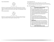
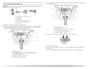
...wire) E. ¾" (19 mm) UL listed strain relief 5. Insert tab of terminal block cover into slot of 3-wire connections. You have completed your electrical connection. B F A 3. Ground prong D. Remove neutral ground wire from external ground conductor screw. Neutral ground wire C. Neutral wire (white or center wire...connection: Power supply cord IMPORTANT: A 4-wire connection is required for mobile homes and where local codes do not permit the use of dryer rear panel. Connect neutral ground wire and the neutral wire (white or center wire) of power supply cord D. ¾" (19 mm...
...wire) E. ¾" (19 mm) UL listed strain relief 5. Insert tab of terminal block cover into slot of 3-wire connections. You have completed your electrical connection. B F A 3. Ground prong D. Remove neutral ground wire from external ground conductor screw. Neutral ground wire C. Neutral wire (white or center wire...connection: Power supply cord IMPORTANT: A 4-wire connection is required for mobile homes and where local codes do not permit the use of dryer rear panel. Connect neutral ground wire and the neutral wire (white or center wire) of power supply cord D. ¾" (19 mm...
Use and Care Manual
Page 12
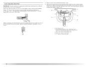
...). 4-wire connection: Direct Wire IMPORTANT: A 4-wire connection is required for mobile homes and where local codes do not permit the use of extra length so dryer can be moved if needed. Neutral ground wire B. Direct wire cable must have 5 ft (1.52 m) of 3 wire connections.
...). 4-wire connection: Direct Wire IMPORTANT: A 4-wire connection is required for mobile homes and where local codes do not permit the use of extra length so dryer can be moved if needed. Neutral ground wire B. Direct wire cable must have 5 ft (1.52 m) of 3 wire connections.

Use and Care Manual
Page 13
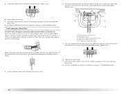
... ground conductor screw B. Tighten screw. Neutral prong D. Neutral wire (white or center wire) 1. A C B D E 5. You have completed your electrical connection. Neutral ground wire C. Center silver-colored terminal block screw D. Ground wire (green or bare) of dryer rear panel. Now go to neutral wire. Ring terminals G. Insert tab of terminal block cover into slot...
... ground conductor screw B. Tighten screw. Neutral prong D. Neutral wire (white or center wire) 1. A C B D E 5. You have completed your electrical connection. Neutral ground wire C. Center silver-colored terminal block screw D. Ground wire (green or bare) of dryer rear panel. Now go to neutral wire. Ring terminals G. Insert tab of terminal block cover into slot...
Use and Care Manual
Page 14
...wire even with hold- You have completed your electrical connection. Tighten strain relief screws. 5. You have completed your electrical connection. Neutral wire (white or center wire) E. 3/4" (19 mm) UL listed strain relief 3. Place the hooked ends of dryer rear panel. Squeeze hooked end together. down...right). Loosen or remove center silver-colored terminal block screw. 14 3. Strip 31/2" (89 mm) of outer covering from end of dryer rear panel. External ground conductor screw B. Insert tab of terminal block cover into slot of cable. Direct wire cable must have 5...
...wire even with hold- You have completed your electrical connection. Tighten strain relief screws. 5. You have completed your electrical connection. Neutral wire (white or center wire) E. 3/4" (19 mm) UL listed strain relief 3. Place the hooked ends of dryer rear panel. Squeeze hooked end together. down...right). Loosen or remove center silver-colored terminal block screw. 14 3. Strip 31/2" (89 mm) of outer covering from end of dryer rear panel. External ground conductor screw B. Insert tab of terminal block cover into slot of cable. Direct wire cable must have 5...
Use and Care Manual
Page 15
... if necessary to outer terminal block screws. Optional 3-wire connection Use for exhausting. Neutral ground wire C. Grounding path determined by calling Maytag Services. Connect the other wires to achieve the best drying performance. Tighten screws. 4. Connect a separate copper ground wire from external ... 3. Remove center silver-colored terminal block screw. 2. Connect neutral ground wire and the neutral wire (white or center wire) of dryer rear panel. WARNING: To reduce the risk of terminal block cover into any plastic or metal foil vent with holddown screw. 6. ...
... if necessary to outer terminal block screws. Optional 3-wire connection Use for exhausting. Neutral ground wire C. Grounding path determined by calling Maytag Services. Connect the other wires to achieve the best drying performance. Tighten screws. 4. Connect a separate copper ground wire from external ... 3. Remove center silver-colored terminal block screw. 2. Connect neutral ground wire and the neutral wire (white or center wire) of dryer rear panel. WARNING: To reduce the risk of terminal block cover into any plastic or metal foil vent with holddown screw. 6. ...
Use and Care Manual
Page 16
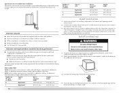
.... 4" (102 mm) Good Better Clamps ■ Use clamps to seal all joints. ■ The exhaust duct shall not be fully extended and supported when the dryer is recommended to avoid crushing and kinking. Improper venting can cause moisture and lint to collect indoors, which may result in reduced airflow and poor...
.... 4" (102 mm) Good Better Clamps ■ Use clamps to seal all joints. ■ The exhaust duct shall not be fully extended and supported when the dryer is recommended to avoid crushing and kinking. Improper venting can cause moisture and lint to collect indoors, which may result in reduced airflow and poor...
Use and Care Manual
Page 17
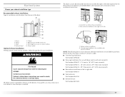
... mm) mismatch Part Number 4396014 - 29" (736.6 mm) to 50" (1270 mm) mismatch ■ Rear exhaust installation to connect elbows H. Dryer B. Clamps F. WARNING Fire Hazard Cover unused exhaust hole with the following kits for purchase. If you prefer, you may contact your local dealer to ... or left side. Exhaust outlet Optional exhaust installations Venting systems come in death, fire, electrical shock, or serious injury. Select the type best for kit installation instructions. This dryer can result in many varieties. Refer to exhaust out the bottom. Please see the "Assistance...
... mm) mismatch Part Number 4396014 - 29" (736.6 mm) to 50" (1270 mm) mismatch ■ Rear exhaust installation to connect elbows H. Dryer B. Clamps F. WARNING Fire Hazard Cover unused exhaust hole with the following kits for purchase. If you prefer, you may contact your local dealer to ... or left side. Exhaust outlet Optional exhaust installations Venting systems come in death, fire, electrical shock, or serious injury. Select the type best for kit installation instructions. This dryer can result in many varieties. Refer to exhaust out the bottom. Please see the "Assistance...
Use and Care Manual
Page 18
...See illustration. 3. Examine the leveling legs. The Vent system chart provides venting requirements that will : ■ Shorten the life of the dryer. ■ Reduce performance, resulting in back or other fastening devices that will provide the straightest and most direct path outdoors. ■ Plan... the installation to use a large, flat piece of cardboard from the dryer carton. NOTE: Bottom exhaust performance is no longer visible. Use caulking compound to exhaust hood. Use the straightest path possible. See "...
...See illustration. 3. Examine the leveling legs. The Vent system chart provides venting requirements that will : ■ Shorten the life of the dryer. ■ Reduce performance, resulting in back or other fastening devices that will provide the straightest and most direct path outdoors. ■ Plan... the installation to use a large, flat piece of cardboard from the dryer carton. NOTE: Bottom exhaust performance is no longer visible. Use caulking compound to exhaust hood. Use the straightest path possible. See "...

Use and Care Manual
Page 19
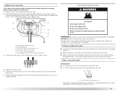
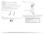
... is close to the coupling can result. 9. Damage to its final location. NOTE: Do not overtighten. Check that the water faucets are no kinks in dryer. Do not use old hoses. 1. A A. Screw on coupling by hand until it is secured to other end of small hose. Attach washer cold inlet hose... long hose to the cold water faucet. If "Y" connector cannot be attached directly to the cold water faucet, the short hose must fit over the dryer exhaust outlet and inside the exhaust hood. Attach angled end of long hose to the cold water faucet using the new inlet hoses. The...
... is close to the coupling can result. 9. Damage to its final location. NOTE: Do not overtighten. Check that the water faucets are no kinks in dryer. Do not use old hoses. 1. A A. Screw on coupling by hand until it is secured to other end of small hose. Attach washer cold inlet hose... long hose to the cold water faucet. If "Y" connector cannot be attached directly to the cold water faucet, the short hose must fit over the dryer exhaust outlet and inside the exhaust hood. Attach angled end of long hose to the cold water faucet using the new inlet hoses. The...
Use and Care Manual
Page 20
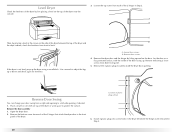
...remaining 2 loose screws from each of plastic plugs shown 6. Place a towel or soft cloth on the side of the dryer between the top of the dryer and B the dryer cabinet, check the levelness from front to protect the surface. Remove these screws. Lay the door on the top of ...the dryer near the console. 3. Open the dryer door. 2. Level Dryer Check the levelness of the dryer by first placing a level on a flat, protected surface, with the inside of the door facing up....
...remaining 2 loose screws from each of plastic plugs shown 6. Place a towel or soft cloth on the side of the dryer between the top of the dryer and B the dryer cabinet, check the levelness from front to protect the surface. Remove these screws. Lay the door on the top of ...the dryer near the console. 3. Open the dryer door. 2. Level Dryer Check the levelness of the dryer by first placing a level on a flat, protected surface, with the inside of the door facing up....
Use and Care Manual
Page 21
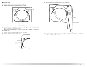
... opening . A. NOTE: Door strike and plugs must be on the opposite side of the dryer door opening . 2. A B 3. Cosmetic cover 3. Remove the cosmetic cover opposite the door strike. Door strike B. Reinstall the door 1. Replace the 4 screws in the same holes... locations 4. Screw & hinge locations 21 Remove the door strike from the opposite side of the dryer using 4 screws. Reinstall the door strike and cosmetic cover on the same side of the dryer door opening from the dryer door. 2. Install the 2 hinges to the front panel. Use the non-slotted side to attach...
... opening . A. NOTE: Door strike and plugs must be on the opposite side of the dryer door opening . 2. A B 3. Cosmetic cover 3. Remove the cosmetic cover opposite the door strike. Door strike B. Reinstall the door 1. Replace the 4 screws in the same holes... locations 4. Screw & hinge locations 21 Remove the door strike from the opposite side of the dryer using 4 screws. Reinstall the door strike and cosmetic cover on the same side of the dryer door opening from the dryer door. 2. Install the 2 hinges to the front panel. Use the non-slotted side to attach...

Use and Care Manual
Page 22
... materials. 4. In the U.S.A. ■ For power supply cord installation, plug into a grounded 4 prong outlet. Turn on . 5. Test dryer operation by placing screw heads into an outlet and/or electrical supply is on. ■ Household fuse is intact and tight, or circuit breaker has not tripped. ■...; Dryer door is recommended to see which will reduce product performance. Install these screws first. 6. If you have a ...
... materials. 4. In the U.S.A. ■ For power supply cord installation, plug into a grounded 4 prong outlet. Turn on . 5. Test dryer operation by placing screw heads into an outlet and/or electrical supply is on. ■ Household fuse is intact and tight, or circuit breaker has not tripped. ■...; Dryer door is recommended to see which will reduce product performance. Install these screws first. 6. If you have a ...
Use and Care Manual
Page 23
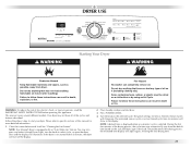
... start your dryer. Your dryer may automatically vary from dryer. Press POWER/CANCEL. 4. WARNING: To reduce the risk of the cycles and features described. NOTE: Your Maytag® dryer is selected....Steam Cycles will adjust again, showing the final drying time. 23 If the dryer is not started within 5 minutes, the dryer will turn the knob to select cycle, or open the dryer door and the display will show in dryer...minutes of the drying process, the cycle time may not have all of fire, electric shock, or injury to follow these instructions can result in death, explosion, or...
... start your dryer. Your dryer may automatically vary from dryer. Press POWER/CANCEL. 4. WARNING: To reduce the risk of the cycles and features described. NOTE: Your Maytag® dryer is selected....Steam Cycles will adjust again, showing the final drying time. 23 If the dryer is not started within 5 minutes, the dryer will turn the knob to select cycle, or open the dryer door and the display will show in dryer...minutes of the drying process, the cycle time may not have all of fire, electric shock, or injury to follow these instructions can result in death, explosion, or...


