

Door Reversal Instructions
Page 1
... death or electrical shock. 1. Remove top screws from dryer cabinet side of dryer. Electrical Shock Hazard Disconnect power before removing doors. Remove bottom screws from dryer cabinet. NOTE: Do not pry apart with a side-opening , if desired. DRYER DOOR REVERSAL INSTRUCTIONS Tools Needed Flat-blade screwdriver Plastic putty knife Minimum 8" long TORX® T25® #2 Phillips screwdriver star driver You can change your door swing from a right-side opening to door. 2. Holding door over...
... death or electrical shock. 1. Remove top screws from dryer cabinet side of dryer. Electrical Shock Hazard Disconnect power before removing doors. Remove bottom screws from dryer cabinet. NOTE: Do not pry apart with a side-opening , if desired. DRYER DOOR REVERSAL INSTRUCTIONS Tools Needed Flat-blade screwdriver Plastic putty knife Minimum 8" long TORX® T25® #2 Phillips screwdriver star driver You can change your door swing from a right-side opening to door. 2. Holding door over...

Owners Manual
Page 2
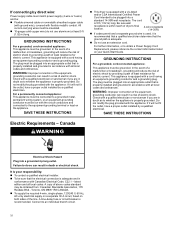
... codes. − Do not install a clothes dryer with clothes dryers. "Risk of Fire" − Clothes dryer installation must be easily crushed, and trap lint. This symbol alerts you don't follow the safety alert symbol and either the word "DANGER" or "WARNING." All safety messages will follow instructions. WARNING You can be performed by the appliance manufacturer as suitable for use with flexible plastic venting...
... codes. − Do not install a clothes dryer with clothes dryers. "Risk of Fire" − Clothes dryer installation must be easily crushed, and trap lint. This symbol alerts you don't follow the safety alert symbol and either the word "DANGER" or "WARNING." All safety messages will follow instructions. WARNING You can be performed by the appliance manufacturer as suitable for use with flexible plastic venting...

Owners Manual
Page 3
... fire. Avoid stopping a tumble dryer before the end of the drying cycle unless all instructions before or after each load. � Keep area around the exhaust opening and adjacent surrounding areas free from service or discarded, remove the door to the drying compartment. � Do not reach into the appliance if the drum is moving. � Do not install or store this appliance where...
... fire. Avoid stopping a tumble dryer before the end of the drying cycle unless all instructions before or after each load. � Keep area around the exhaust opening and adjacent surrounding areas free from service or discarded, remove the door to the drying compartment. � Do not reach into the appliance if the drum is moving. � Do not install or store this appliance where...

Owners Manual
Page 4
... a circuit different from that to which can be guided through the steps to set up a user account and to use is connected. � Consult the dealer or an experienced radio/TV technician for Connected Appliances Only IMPORTANT: Proper installation of the device. This device may apply. Changes or modifications not expressly approved by Industry Canada. This device may only operate using...
... a circuit different from that to which can be guided through the steps to set up a user account and to use is connected. � Consult the dealer or an experienced radio/TV technician for Connected Appliances Only IMPORTANT: Proper installation of the device. This device may apply. Changes or modifications not expressly approved by Industry Canada. This device may only operate using...

Owners Manual
Page 5
... avoid transfer of the dryer. Use a microfiber cloth and very warm water in front of dye. Dry unstable dye items inside the dryer cabinet: Lint should be done by lint can increase drying time. 2. Removing Accumulated Lint From inside out to dry. Cleaning the Lint Screen Every load cleaning: The lint screen may discolor the rear of lint screen with a clean towel. See "Venting Requirements" in the Installation Instructions. � Clean space where lint screen is located, as needed cleaning: Laundry detergent and fabric...
... avoid transfer of the dryer. Use a microfiber cloth and very warm water in front of dye. Dry unstable dye items inside the dryer cabinet: Lint should be done by lint can increase drying time. 2. Removing Accumulated Lint From inside out to dry. Cleaning the Lint Screen Every load cleaning: The lint screen may discolor the rear of lint screen with a clean towel. See "Venting Requirements" in the Installation Instructions. � Clean space where lint screen is located, as needed cleaning: Laundry detergent and fabric...

Owners Manual
Page 6
... power. 2. Plug in good airflow. The venting system attached to efficiently dry laundry. When cleaning is complete, be on vacation or not using your lint screen before moving dryer. Steam Models Only: Turn off power at least every 2 years. Steam models only: Shut off water faucet. Transport hose separately. 3. Steam models only: Shut off water faucet. On models with base trim, remove base trim before moving dryer. Open the dryer door. Locate the light bulb cover on some models)" for details. Replace the bulb with heat, dryers require...
... power. 2. Plug in good airflow. The venting system attached to efficiently dry laundry. When cleaning is complete, be on vacation or not using your lint screen before moving dryer. Steam Models Only: Turn off power at least every 2 years. Steam models only: Shut off water faucet. Transport hose separately. 3. Steam models only: Shut off water faucet. On models with base trim, remove base trim before moving dryer. Open the dryer door. Locate the light bulb cover on some models)" for details. Replace the bulb with heat, dryers require...

Owners Manual
Page 7
... your dryer. Turn on some water may vary according to model) Parts package is located in the Installation Instructions. Gather required tools and parts before starting installation. Parts Needed (steam models): "Y" connector Rubber washer Pliers Tape measure 2' (0.6 m) inlet hose 5' (1.52 m) inlet hose 7 Disconnect water inlet hose from faucet and drain. Flush water pipes. Special Instructions for All Installations: Utility knife Tin snips Caulking gun and compound Adjustable wrench that all models): Flat-blade screwdriver Wire stripper 1/4" Nut driver...
... your dryer. Turn on some water may vary according to model) Parts package is located in the Installation Instructions. Gather required tools and parts before starting installation. Parts Needed (steam models): "Y" connector Rubber washer Pliers Tape measure 2' (0.6 m) inlet hose 5' (1.52 m) inlet hose 7 Disconnect water inlet hose from faucet and drain. Flush water pipes. Special Instructions for All Installations: Utility knife Tin snips Caulking gun and compound Adjustable wrench that all models): Flat-blade screwdriver Wire stripper 1/4" Nut driver...

Owners Manual
Page 8
... electric dryers. � If you purchased your installation. Vented Models: Vent Clamps, elbows, and vent work Parts Needed (not supplied with equivalent ventilation openings can result in an area where it (even after washing). Available Accessories: Accessories and replacement parts are using power supply cord, a grounded electrical outlet located within 4 ft (1.2 m) of the water fill valves, and water pressure of automatic sensor cycles, resulting in garages, closets, mobile homes, or sleeping quarters. Do not dry...
... electric dryers. � If you purchased your installation. Vented Models: Vent Clamps, elbows, and vent work Parts Needed (not supplied with equivalent ventilation openings can result in an area where it (even after washing). Available Accessories: Accessories and replacement parts are using power supply cord, a grounded electrical outlet located within 4 ft (1.2 m) of the water fill valves, and water pressure of automatic sensor cycles, resulting in garages, closets, mobile homes, or sleeping quarters. Do not dry...

Owners Manual
Page 9
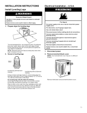
... a location where grounding through the neutral conductor is prohibited for mobile home installations. The opening . latest edition and all mobile home installations. Electrical Connection To properly install your outlet looks like this : 4-wire receptacle (14-30R) Then choose a 4-wire power supply cord with a 3-wire electrical supply connection. If the local electrical codes require the use with clothes dryers. When the neutral bond conductor is secured under the neutral terminal (center or white wire...
... a location where grounding through the neutral conductor is prohibited for mobile home installations. The opening . latest edition and all mobile home installations. Electrical Connection To properly install your outlet looks like this : 4-wire receptacle (14-30R) Then choose a 4-wire power supply cord with a 3-wire electrical supply connection. If the local electrical codes require the use with clothes dryers. When the neutral bond conductor is secured under the neutral terminal (center or white wire...
Owners Manual
Page 10
... of electric shock. Failure to a grounded metal, permanent wiring system, or an equipment-grounding conductor must match power supply (4-wire or 3-wire) and be plugged into a grounded 4 prong outlet. For a permanently connected appliance: This appliance must be connected to do not use an extension cord. The plug must be grounded. For further information, or to an individual branch circuit. 10 GROUNDING INSTRUCTIONS For a grounded, cord-connected appliance...
... of electric shock. Failure to a grounded metal, permanent wiring system, or an equipment-grounding conductor must match power supply (4-wire or 3-wire) and be plugged into a grounded 4 prong outlet. For a permanently connected appliance: This appliance must be connected to do not use an extension cord. The plug must be grounded. For further information, or to an individual branch circuit. 10 GROUNDING INSTRUCTIONS For a grounded, cord-connected appliance...
Owners Manual
Page 11
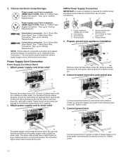
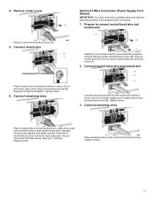
... power 2. Firmly grasp dryer body (not console panel) and gently lay dryer down screw and terminal block cover. 11 Connect remaining 2 supply wires to green ground connector. Leave enough room to 11/2" (38 mm) from dryer packaging under entire back edge of the dryer. WARNING Fire Hazard For power supply cord, use 10 gauge copper wire. Remove hold-down on its final location. Use a UL listed strain relief. Remove terminal block cover NOTE: Your terminal block cover...
... power 2. Firmly grasp dryer body (not console panel) and gently lay dryer down screw and terminal block cover. 11 Connect remaining 2 supply wires to green ground connector. Leave enough room to 11/2" (38 mm) from dryer packaging under entire back edge of the dryer. WARNING Fire Hazard For power supply cord, use 10 gauge copper wire. Remove hold-down on its final location. Use a UL listed strain relief. Remove terminal block cover NOTE: Your terminal block cover...
Owners Manual
Page 12
... "Venting Requirements." 3-wire direct connection: Go to "Direct Wire Strain Relief", then "3-Wire Direct Wire Connection," then, go to "Venting Requirements." Connect ground wire Put power supply cord through the strain relief. Then, go to "4-Wire Power Supply Connection". NOTE: If local codes do not permit the use of power supply cord under green external ground conductor screw (A). Power Supply Cord Connection Power Supply Cord Strain Relief 1. Tighten screw. 12 3. The strain relief should have a tight fit with the dryer...
... "Venting Requirements." 3-wire direct connection: Go to "Direct Wire Strain Relief", then "3-Wire Direct Wire Connection," then, go to "Venting Requirements." Connect ground wire Put power supply cord through the strain relief. Then, go to "4-Wire Power Supply Connection". NOTE: If local codes do not permit the use of power supply cord under green external ground conductor screw (A). Power Supply Cord Connection Power Supply Cord Strain Relief 1. Tighten screw. 12 3. The strain relief should have a tight fit with the dryer...
Owners Manual
Page 13
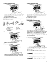
... type 10-30R) B. 3-wire plug C. Neutral (white or center wire) Unscrew the removable conduit connector (A) and any screws from a 3/4" (19 mm) UL-listed strain relief (UL marking on strain relief). Attach direct wire cable to "4-Wire Direct Wire Connection." The strain relief should have a tight fit with upturned ends 3. For 3-wire Direct Wire Connection, continue to step 3. 3-wire direct wire connection: Go to "3-Wire Direct Wire Connection." 13 Insert tab of terminal block cover into slot of dryer rear panel. Spade terminals...
... type 10-30R) B. 3-wire plug C. Neutral (white or center wire) Unscrew the removable conduit connector (A) and any screws from a 3/4" (19 mm) UL-listed strain relief (UL marking on strain relief). Attach direct wire cable to "4-Wire Direct Wire Connection." The strain relief should have a tight fit with upturned ends 3. For 3-wire Direct Wire Connection, continue to step 3. 3-wire direct wire connection: Go to "3-Wire Direct Wire Connection." 13 Insert tab of terminal block cover into slot of dryer rear panel. Spade terminals...
Owners Manual
Page 14
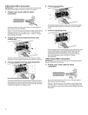
... terminal block screws (hooks facing right). Shape wire ends into hooks. 4. Strip 5" (127 mm) of outer covering from end of dryer rear panel. Tighten screw. 7. Squeeze hooked ends together and tighten screws. Strip 31/2" (89 mm) of outer covering from end of remaining direct wire cable wires under center screw of wires into hooks. 14 Shape ends of terminal block (B). Connect ground wire Direct wire cable must have 5 ft (1.52 m) of extra length so dryer...
... terminal block screws (hooks facing right). Shape wire ends into hooks. 4. Strip 5" (127 mm) of outer covering from end of dryer rear panel. Tighten screw. 7. Squeeze hooked ends together and tighten screws. Strip 31/2" (89 mm) of outer covering from end of remaining direct wire cable wires under center screw of wires into hooks. 14 Shape ends of terminal block (B). Connect ground wire Direct wire cable must have 5 ft (1.52 m) of extra length so dryer...
Owners Manual
Page 15
... wire (white or center) (C) of remaining direct wire cable wires under center terminal block screw (B). Tighten screw. 6. Tighten screw. 3. Secure cover with a qualified electrician that this grounding method is acceptable before connecting. 1. Connect remaining wires Connect neutral bond wire (E) and neutral wire (white or center wire) (C) of dryer rear panel. Insert tab of terminal block cover into slot of power supply cord or cable under outer terminal block screws. Remove center screw Remove center terminal block screw (B). 5. Squeeze hooked...
... wire (white or center) (C) of remaining direct wire cable wires under center terminal block screw (B). Tighten screw. 6. Tighten screw. 3. Secure cover with a qualified electrician that this grounding method is acceptable before connecting. 1. Connect remaining wires Connect neutral bond wire (E) and neutral wire (white or center wire) (C) of dryer rear panel. Insert tab of terminal block cover into slot of power supply cord or cable under outer terminal block screws. Remove center screw Remove center terminal block screw (B). 5. Squeeze hooked...

Owners Manual
Page 16
... the home is not plugged with hold-down screw. Rigid metal vent: � Recommended for exhausting. Connect external ground wire Connect a separate copper ground wire (G) from the entire length of the system before installing the dryer. � Make sure external exhaust hoods outside debris. � Replace plastic of duct and catch lint. Failure to follow these instructions can be used for best drying performance and to an...
... the home is not plugged with hold-down screw. Rigid metal vent: � Recommended for exhausting. Connect external ground wire Connect a separate copper ground wire (G) from the entire length of the system before installing the dryer. � Make sure external exhaust hoods outside debris. � Replace plastic of duct and catch lint. Failure to follow these instructions can be used for best drying performance and to an...

Owners Manual
Page 17
... to connect elbows H. A. Standard rear offset exhaust installation B. Dryer B. Optional side exhaust outlet Optional exhaust installations: WARNING Fire Hazard Cover unused exhaust holes with one 90º turn inside the dryer. Bottom exhaust installation (available only on select 27"-wide models). To determine maximum exhaust length, add one offset elbow) Periscope installation Special provisions for contact information. Other installations are available for close -clearance installations are shown. Vent length necessary to use fewest number of vent...
... to connect elbows H. A. Standard rear offset exhaust installation B. Dryer B. Optional side exhaust outlet Optional exhaust installations: WARNING Fire Hazard Cover unused exhaust holes with one 90º turn inside the dryer. Bottom exhaust installation (available only on select 27"-wide models). To determine maximum exhaust length, add one offset elbow) Periscope installation Special provisions for contact information. Other installations are available for close -clearance installations are shown. Vent length necessary to use fewest number of vent...

Owners Manual
Page 18
... 110 ft (33.5 m) To determine if your model has a long vent system, refer to the type code located on the serial number plate in which the Installation Instructions do not address the vent length for the specific number of elbows required for future reference. Do not use of box/louvered hoods will improve venting regardless of the 2 ft (0.6 m) inlet hose. Damage to seal all straight and curved portions...
... 110 ft (33.5 m) To determine if your model has a long vent system, refer to the type code located on the serial number plate in which the Installation Instructions do not address the vent length for the specific number of elbows required for future reference. Do not use of box/louvered hoods will improve venting regardless of the 2 ft (0.6 m) inlet hose. Damage to seal all straight and curved portions...
Owners Manual
Page 19
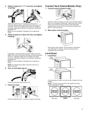
... valve connector. If connecting to other end of "Y" connector. Attach other side of long hose to exhaust outlet Attach one of dryer from under dryer. NOTE: Do not overtighten. Turn on dryer back panel. Repeat from water inlet valve. Connect vent to fill valve on cold water faucet Move dryer to "Y" connector and tighten Connect Vent (Vented Models Only) couplings 1. Screw on . 7. Using pliers, tighten the couplings an additional two-thirds turn . Damage to operate correctly. Level Dryer Check that vent...
... valve connector. If connecting to other end of "Y" connector. Attach other side of long hose to exhaust outlet Attach one of dryer from under dryer. NOTE: Do not overtighten. Turn on dryer back panel. Repeat from water inlet valve. Connect vent to fill valve on cold water faucet Move dryer to "Y" connector and tighten Connect Vent (Vented Models Only) couplings 1. Screw on . 7. Using pliers, tighten the couplings an additional two-thirds turn . Damage to operate correctly. Level Dryer Check that vent...

Owners Manual
Page 20
... Air Only temperature setting. If the dryer will not start dryer. If there is first used. Be sure vent is not crushed or kinked. � Check that all of lime scale may lead to the need for certain part replacement or repair. � To change the door swing from dryer and remove. Over time, the buildup of your dryer vent may be crushed or blocked. 20 This odor is common when heating element...
... Air Only temperature setting. If the dryer will not start dryer. If there is first used. Be sure vent is not crushed or kinked. � Check that all of lime scale may lead to the need for certain part replacement or repair. � To change the door swing from dryer and remove. Over time, the buildup of your dryer vent may be crushed or blocked. 20 This odor is common when heating element...


