

Owners Manual
Page 2
...control. Use personal protective equipment. Always wear eye protection. Protective equipment such as pipes, radiators, ranges and refrigerators. Carrying power tools with your body is unavoidable, use reduces the risk of electric shock. 8. Do not overreach. Do not wear loose clothing or... the connection of drugs, alcohol or medication. If devices are connected and properly used for future reference. Water entering a power tool will increase the risk of electric shock. 5. Unmodified plugs and matching outlets will reduce personal injuries. 12. Failure to your ...
...control. Use personal protective equipment. Always wear eye protection. Protective equipment such as pipes, radiators, ranges and refrigerators. Carrying power tools with your body is unavoidable, use reduces the risk of electric shock. 8. Do not overreach. Do not wear loose clothing or... the connection of drugs, alcohol or medication. If devices are connected and properly used for future reference. Water entering a power tool will increase the risk of electric shock. 5. Unmodified plugs and matching outlets will reduce personal injuries. 12. Failure to your ...
Owners Manual
Page 3
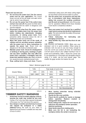
...Inspect for misalignment or binding of moving parts, breakage of children and do the job better and safer at the rate for your power tool serviced by insulated gripping surfaces, 5. Make sure the bit is not contacting the workpiece before operation. Disconnect the plug from the power source... gage. platform.Holding the work to loss of control. 16 14 12 12 Not Recommended Wear hearing protection during extended period of the power tool "live " wire may contact its own cord. against the body leaves it was designed. 18. Check for and remove all nails from rotating...
...Inspect for misalignment or binding of moving parts, breakage of children and do the job better and safer at the rate for your power tool serviced by insulated gripping surfaces, 5. Make sure the bit is not contacting the workpiece before operation. Disconnect the plug from the power source... gage. platform.Holding the work to loss of control. 16 14 12 12 Not Recommended Wear hearing protection during extended period of the power tool "live " wire may contact its own cord. against the body leaves it was designed. 18. Check for and remove all nails from rotating...

Owners Manual
Page 4
... of the correct shank diameter suitable for the bit to come to follow the safety rules stated in the tool base. 16. MISUSE or failure to a complete stop the tool, press the "OFF (O)" side of the bit rotating direction and the feed direction. 12. Watch for obtaining... constant speed. SAVE THESE INSTRUCTIONS. Before using the tool on the tool. Operate the tool only when hand-held. 13. They may be toxic. Tool base 3. After adjusting, tighten the locking lever firmly to prevent dust inhalation and skin contact.
... of the correct shank diameter suitable for the bit to come to follow the safety rules stated in the tool base. 16. MISUSE or failure to a complete stop the tool, press the "OFF (O)" side of the bit rotating direction and the feed direction. 12. Watch for obtaining... constant speed. SAVE THESE INSTRUCTIONS. Before using the tool on the tool. Operate the tool only when hand-held. 13. They may be toxic. Tool base 3. After adjusting, tighten the locking lever firmly to prevent dust inhalation and skin contact.
Owners Manual
Page 5
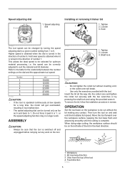
... obtained when it past 6 or 1, or the speed adjusting function may no longer work on the workpiece to 1. Loosen 3. OPERATION Set the tool base on the tool. 011837 1 3 2 1. Workpiece 2. View from 1 to suit the material and bit diameter. Feed direction 001984 5 Speed adjusting dial Installing or ...to a given number setting from the top of number 1. When doing edge cutting, the workpiece surface should be sure that the tool is turned in tool malfunction. • The speed adjusting dial can be changed by pressing the shaft lock and using the provided wrench. Shaft lock ...
... obtained when it past 6 or 1, or the speed adjusting function may no longer work on the workpiece to 1. Loosen 3. OPERATION Set the tool base on the tool. 011837 1 3 2 1. Workpiece 2. View from 1 to suit the material and bit diameter. Feed direction 001984 5 Speed adjusting dial Installing or ...to a given number setting from the top of number 1. When doing edge cutting, the workpiece surface should be sure that the tool is turned in tool malfunction. • The speed adjusting dial can be changed by pressing the shaft lock and using the provided wrench. Shaft lock ...
Owners Manual
Page 6
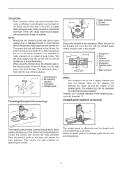
...(X) = (outside of the templet guide. Workpiece 6. Base protector 011982 NOTE: • The workpiece will help to keep it on the right side in controlling the tool, the depth of cut should not be sure to keep it is effectively used for the distance (X) between the router bit and the outside diameter... guide provides a sleeve through which the bit passes, allowing use of the trimmer with the bolt and the wing nut. 6 NOTE: • Moving the tool forward too fast may cause a poor quality of cut . This will show exactly how the cut will depend on the bit size, the kind of...
...(X) = (outside of the templet guide. Workpiece 6. Base protector 011982 NOTE: • The workpiece will help to keep it on the right side in controlling the tool, the depth of cut should not be sure to keep it is effectively used for the distance (X) between the router bit and the outside diameter... guide provides a sleeve through which the bit passes, allowing use of the trimmer with the bolt and the wing nut. 6 NOTE: • Moving the tool forward too fast may cause a poor quality of cut . This will show exactly how the cut will depend on the bit size, the kind of...
Owners Manual
Page 7
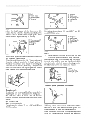
... Min. radius of circles to the workpiece and use it as a guide against the trimmer base. Guide plate 3. Loosen the wing nut on the tool base with the clamp screw (A). At the desired distance, tighten the wing nut securely. 1 2 1. In this guide. Center hole 3. Straight guide...be cut . Drive a nail less than 6 mm (1/4") in radius. 1. 1 1. Guide plate 1 2. Center hole 5. Feed the tool in clockwise direction. 1. Pivot the tool around the nail in the direction of the circle to secure the straight guide. Straight guide 1 2 3 011842 Circular work Circular work may...
... Min. radius of circles to the workpiece and use it as a guide against the trimmer base. Guide plate 3. Loosen the wing nut on the tool base with the clamp screw (A). At the desired distance, tighten the wing nut securely. 1 2 1. In this guide. Center hole 3. Straight guide...be cut . Drive a nail less than 6 mm (1/4") in radius. 1. 1 1. Guide plate 1 2. Center hole 5. Feed the tool in clockwise direction. 1. Pivot the tool around the nail in the direction of the circle to secure the straight guide. Straight guide 1 2 3 011842 Circular work Circular work may...
Owners Manual
Page 8
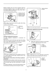
... (1) Offset base (optional accessory) is convenient for work in place. 1 1. Shaft lock 1 2 3 011985 8 Adjusting screw 2 3. Base protector 1 2. Workpiece 2 2. Place the tool onto the tilt base and close the locking lever at the desired protrusion of the workpiece. 1. For another application, remove the base protector from the...riding the side of the bit. For desired angle, tighten the clamping screws on the trimmer base. Pulley 3. Feed the tool in the direction of the trimmer base from the tilt base on the offset base, remove the collet nut and collet cone ...
... (1) Offset base (optional accessory) is convenient for work in place. 1 1. Shaft lock 1 2 3 011985 8 Adjusting screw 2 3. Base protector 1 2. Workpiece 2 2. Place the tool onto the tilt base and close the locking lever at the desired protrusion of the workpiece. 1. For another application, remove the base protector from the...riding the side of the bit. For desired angle, tighten the clamping screws on the trimmer base. Pulley 3. Feed the tool in the direction of the trimmer base from the tilt base on the offset base, remove the collet nut and collet cone ...

Owners Manual
Page 9
...width fits over the pulley using a screwdriver and make sure that position, insert the bit into the hole in the figure. 011860 Mount the tool on the offset base 1 1. Trimmer base assembly (optional 3 accessory) 011935 Mount the trimmer base with four screws and the grip attachment (...optional accessory) with a wrench. 1 2 1. Wrench 2. Install the pulley on the tool by pressing the shaft lock and firmly tightening the pulley with two screws on the offset base plate. 9 Bit 2 011859 Place the collet cone and...
...width fits over the pulley using a screwdriver and make sure that position, insert the bit into the hole in the figure. 011860 Mount the tool on the offset base 1 1. Trimmer base assembly (optional 3 accessory) 011935 Mount the trimmer base with four screws and the grip attachment (...optional accessory) with a wrench. 1 2 1. Wrench 2. Install the pulley on the tool by pressing the shaft lock and firmly tightening the pulley with two screws on the offset base plate. 9 Bit 2 011859 Place the collet cone and...
Owners Manual
Page 10
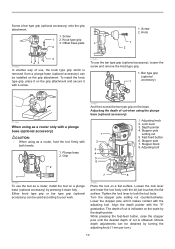
...1 2 3 4 5 6 1. Grip 2 011857 And then screw the bar type grip on a flat surface. Loosen the lock lever and lower the tool body until the desired depth of cut is indicated on a plunge base (optional accessory) by the depth pointer. Align the depth pointer with both hands... grip attachment. 1. Offset base plate 2 1. Depth pointer 4. Stopper pole 7. Tighten the lock lever to your work. 7 8 011983 Place the tool on the base. Turn the stopper pole setting nut counterclockwise. Lock lever 3. Knob type grip 3. Lower the stopper pole until it with the adjusting ...
...1 2 3 4 5 6 1. Grip 2 011857 And then screw the bar type grip on a flat surface. Loosen the lock lever and lower the tool body until the desired depth of cut is indicated on a plunge base (optional accessory) by the depth pointer. Align the depth pointer with both hands... grip attachment. 1. Offset base plate 2 1. Depth pointer 4. Stopper pole 7. Tighten the lock lever to your work. 7 8 011983 Place the tool on the base. Turn the stopper pole setting nut counterclockwise. Lock lever 3. Knob type grip 3. Lower the stopper pole until it with the adjusting ...
Owners Manual
Page 11
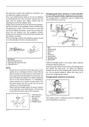
...revolving direction 3. Straight guide 8. To adjust the distance between the bit and the straight guide, loosen the wing nut. Then turn the tool on the actual workpiece, it flush with the wing nut. The proper feed rate will depend on a piece of the bit in the ... 4 1. At the desired distance, tighten the wing nut to secure the straight guide in the plunge base and tighten the wing bolts. Workpiece 2. Set the tool base on the left side of scrap lumber. Workpiece 4. Wing nut 4. This will help to keep it is effectively used for straight cuts when chamfering...
...revolving direction 3. Straight guide 8. To adjust the distance between the bit and the straight guide, loosen the wing nut. Then turn the tool on the actual workpiece, it flush with the wing nut. The proper feed rate will depend on a piece of the bit in the ... 4 1. At the desired distance, tighten the wing nut to secure the straight guide in the plunge base and tighten the wing bolts. Workpiece 2. Set the tool base on the left side of scrap lumber. Workpiece 4. Wing nut 4. This will help to keep it is effectively used for straight cuts when chamfering...

Owners Manual
Page 12
... bars into the holes in place. At the desired distance, tighten the wing bolts to secure the straight guide in the plunge base. Feed the tool in the direction of the templet. 1 7 2 3 4 5 6 1. Base 3. The distance (X) can be cut a slightly different size from ...the templet. Trimmer base 011989 3 2 12 1. Guide bar 1 2. Screw 2. Place the tool on the tool base, insert the templet guide and then tighten the screws. 1 1. Adjust the distance between the side of the workpiece and the cutting position is...
... bars into the holes in place. At the desired distance, tighten the wing bolts to secure the straight guide in the plunge base. Feed the tool in the direction of the templet. 1 7 2 3 4 5 6 1. Base 3. The distance (X) can be cut a slightly different size from ...the templet. Trimmer base 011989 3 2 12 1. Guide bar 1 2. Screw 2. Place the tool on the tool base, insert the templet guide and then tighten the screws. 1 1. Adjust the distance between the side of the workpiece and the cutting position is...
Owners Manual
Page 13
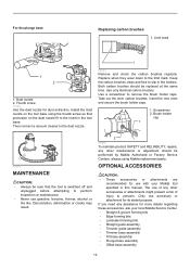
...any other maintenance or adjustment should be sure that protrusion on the dust nozzle fit to persons. Install the dust nozzle on the tool base using Makita replacement parts. Keep the carbon brushes clean and free to remove the brush holder caps. Use a screwdriver to slip in the ...base assembly 13 Thumb screw 011853 Use the dust nozzle for use accessory or attachment for more details regarding these accessories, ask your Makita tool specified in the tool base. Use only identical carbon brushes. Take out the worn carbon brushes, insert the new ones and secure the brush holder ...
...any other maintenance or adjustment should be sure that protrusion on the dust nozzle fit to persons. Install the dust nozzle on the tool base using Makita replacement parts. Keep the carbon brushes clean and free to remove the brush holder caps. Use a screwdriver to slip in the ...base assembly 13 Thumb screw 011853 Use the dust nozzle for use accessory or attachment for more details regarding these accessories, ask your Makita tool specified in the tool base. Use only identical carbon brushes. Take out the worn carbon brushes, insert the new ones and secure the brush holder ...

Owners Manual
Page 14
... Wrench 13 • Wrench 22 • Dust nozzle set NOTE: • Some items in the tool package as standard accessories. MAKITA LIMITED ONE YEAR WARRANTY Warranty Policy Every Makita tool is caused by others: repairs are required because of incidental or consequential damages, so the above limitation may ...have been made to one year period, return the COMPLETE tool, freight prepaid, to the tool. EN0006-1 14 This Warranty does not apply where: repairs have been made or attempted by defective workmanship or material, Makita will repair (or at our option, replace) without ...
... Wrench 13 • Wrench 22 • Dust nozzle set NOTE: • Some items in the tool package as standard accessories. MAKITA LIMITED ONE YEAR WARRANTY Warranty Policy Every Makita tool is caused by others: repairs are required because of incidental or consequential damages, so the above limitation may ...have been made to one year period, return the COMPLETE tool, freight prepaid, to the tool. EN0006-1 14 This Warranty does not apply where: repairs have been made or attempted by defective workmanship or material, Makita will repair (or at our option, replace) without ...

Parts Breakdown
Page 3
A14 831327-5 TOOL BAG 1 A15 196093-4 OFFSET BASE SET 1 A15 222171-5 PULLEY 12-23.1 1 A15 318685-1 GRIP ATTACHMENT 1 A15 912112-6 COUNTERSUNK HEAD SCREW M4X10 2 A15 COMPO-PARTS 0
A14 831327-5 TOOL BAG 1 A15 196093-4 OFFSET BASE SET 1 A15 222171-5 PULLEY 12-23.1 1 A15 318685-1 GRIP ATTACHMENT 1 A15 912112-6 COUNTERSUNK HEAD SCREW M4X10 2 A15 COMPO-PARTS 0
Flyer (English)
Page 2
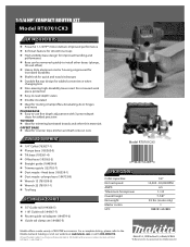
... Straight guide (164834-6) n Trimmer guide (122703-7) n Dust nozzle - fixed base (195559-1) n Dust nozzle - All specifications subject to the Makita General Catalog or visit our website at makitatools.com or call 1-800-4MAKITA. For a complete listing, please refer to change without prior notice.... n Wrench 13 (781039-9) n Wrench 22 (781011-1) n Tool bag OPTIONAL ACCESSORIES n 55" Guide rail (194368-5) n 118" Guide rail (194367-7) n Router guide rail adapter (194579-2) n Guide rail clamp set (194385-5) Model RT0701CX3 0 88381 65288 9 SPECIFICATIONS Collet capacities No load speed AMPS ...
... Straight guide (164834-6) n Trimmer guide (122703-7) n Dust nozzle - fixed base (195559-1) n Dust nozzle - All specifications subject to the Makita General Catalog or visit our website at makitatools.com or call 1-800-4MAKITA. For a complete listing, please refer to change without prior notice.... n Wrench 13 (781039-9) n Wrench 22 (781011-1) n Tool bag OPTIONAL ACCESSORIES n 55" Guide rail (194368-5) n 118" Guide rail (194367-7) n Router guide rail adapter (194579-2) n Guide rail clamp set (194385-5) Model RT0701CX3 0 88381 65288 9 SPECIFICATIONS Collet capacities No load speed AMPS ...
