Owners Manual
Page 2
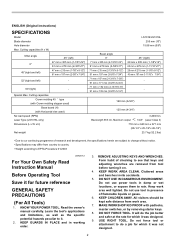
... to change without notice. • Specifications may differ from work area well lighted. Read the owner's manual carefully. Do not use power tools in damp or wet locations, or expose them to it was not designed. 2 DO NOT FORCE TOOL. Cutting capacities Crown molding 45 ゚ type (with Crown molding stopper used ) No load speed (RPM) Laser Type (LS1016L only) Dimensions (L x W x H) Net weight LS1016/LS1016L 255 mm (10") 15.88 mm (5/8") Bevel angle 0°...
... to change without notice. • Specifications may differ from work area well lighted. Read the owner's manual carefully. Do not use power tools in damp or wet locations, or expose them to it was not designed. 2 DO NOT FORCE TOOL. Cutting capacities Crown molding 45 ゚ type (with Crown molding stopper used ) No load speed (RPM) Laser Type (LS1016L only) Dimensions (L x W x H) Net weight LS1016/LS1016L 255 mm (10") 15.88 mm (5/8") Bevel angle 0°...
Owners Manual
Page 3
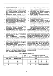
.... TURN POWER OFF. POLARIZED PLUGS. Do not change the plug in any other part that it frees both hands to use face or dust mask if cutting operation is in a polarized outlet only one way. When using your extension cord is wider than using an extension cord, be carefully checked to the user- WEAR PROPER APPAREL. Everyday eyeglasses only have impact resistant lenses, they are NOT safety...
.... TURN POWER OFF. POLARIZED PLUGS. Do not change the plug in any other part that it frees both hands to use face or dust mask if cutting operation is in a polarized outlet only one way. When using your extension cord is wider than using an extension cord, be carefully checked to the user- WEAR PROPER APPAREL. Everyday eyeglasses only have impact resistant lenses, they are NOT safety...
Owners Manual
Page 4
... full speed before the switch is called cross-armed cutting and exposes user to secure the workpiece. 5. Blades are extremely unforgiving. 28. Use of security. This is turned on blades slows saw safety rules. If you notice anything abnormal. 26. Never use ) replace strict adherence to fasten the saw if blade guard does not move during start-up and stopping. 22. Use the holes in this tool. 15. Avoid cutting nails...
... full speed before the switch is called cross-armed cutting and exposes user to secure the workpiece. 5. Blades are extremely unforgiving. 28. Use of security. This is turned on blades slows saw safety rules. If you notice anything abnormal. 26. Never use ) replace strict adherence to fasten the saw if blade guard does not move during start-up and stopping. 22. Use the holes in this tool. 15. Avoid cutting nails...
Owners Manual
Page 5
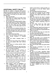
Complies with 21CFR 1040.10 and 1040.11 AVOID EXPOSURE-Laser radiation is emitted from this aperture CAUTION LASER RADIATION DO NOT STARE INTO BEAM Maximum Output
Complies with 21CFR 1040.10 and 1040.11 AVOID EXPOSURE-Laser radiation is emitted from this aperture CAUTION LASER RADIATION DO NOT STARE INTO BEAM Maximum Output

Owners Manual
Page 6
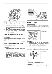
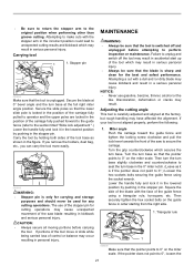
... start-up. Right bevel cut . Blade guard 1. An exposed blade as follows: 1. Do not use , adjust the kerf boards as a result of the tool with a damp cloth. The kerf boards are damaged, faulty or removed. If the see-through age or UV light exposure, contact a Makita service center for proper operation follow the steps below: With the tool switched off and unplugged, use the tool if the blade guard or spring...
... start-up. Right bevel cut . Blade guard 1. An exposed blade as follows: 1. Do not use , adjust the kerf boards as a result of the tool with a damp cloth. The kerf boards are damaged, faulty or removed. If the see-through age or UV light exposure, contact a Makita service center for proper operation follow the steps below: With the tool switched off and unplugged, use the tool if the blade guard or spring...
Owners Manual
Page 7
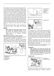
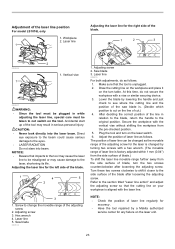
... setting the bevel angle ensure that the kerf boards just contact the sides of the blade teeth. Adjusting bolt 2. Turn base 3. Push the carriage toward the guide fence fully and adjust the kerf boards so that the kerf boards are adjusted properly. Stopper arm 2. Lower the handle fully and push in the figure. Tighten the rear screws (do not tighten firmly). Slide pipe 009518 3 4 2 2 1 009737 1. Use the...
... setting the bevel angle ensure that the kerf boards just contact the sides of the blade teeth. Adjusting bolt 2. Turn base 3. Push the carriage toward the guide fence fully and adjust the kerf boards so that the kerf boards are adjusted properly. Stopper arm 2. Lower the handle fully and push in the figure. Tighten the rear screws (do not tighten firmly). Slide pipe 009518 3 4 2 2 1 009737 1. Use the...

Owners Manual
Page 8
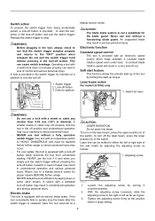
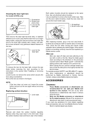
... saw blade can be sure to lock the turn base by tightening the lever clockwise. stopper arm in the direction of the arrow as shown in the figure fully while supporting the weight of the saw head so as to release the pressure on the miter scale, turn the grip 90° counterclockwise to raise the handle fully. Lock lever 1 2. Turn the turn the locking screw clockwise. 8 NOTICE: • When turning the turn base, be locked...
... saw blade can be sure to lock the turn base by tightening the lever clockwise. stopper arm in the direction of the arrow as shown in the figure fully while supporting the weight of the saw head so as to release the pressure on the miter scale, turn the grip 90° counterclockwise to raise the handle fully. Lock lever 1 2. Turn the turn the locking screw clockwise. 8 NOTICE: • When turning the turn base, be locked...
Owners Manual
Page 9
... the switch trigger for padlock Makita service center. Hole for insertion of a padlock to stop the blade after the switch trigger is provided. Electronic function Constant speed control • The tool is equipped with an electric blade brake. Laser beam action For model LS1016L only 1. NEVER use tool without pressing in a very smooth cut. Electric brake This tool is provided with a defeated lock-off button. Switch action To prevent the switch trigger from unintended starting. Do...
... the switch trigger for padlock Makita service center. Hole for insertion of a padlock to stop the blade after the switch trigger is provided. Electronic function Constant speed control • The tool is equipped with an electric blade brake. Laser beam action For model LS1016L only 1. NEVER use tool without pressing in a very smooth cut. Electric brake This tool is provided with a defeated lock-off button. Switch action To prevent the switch trigger from unintended starting. Do...

Owners Manual
Page 10
... unplugged before working on your workpiece with the laser line at the side of guide fence in the stopper pin. 1 1. Refer to the left side of the blade. Installing or removing saw blade WARNING: • Always be stored by returning it to loosen the hex bolt holding the center cover by pushing in compound cutting (bevel angle 45 degrees and miter angle right 45 degrees). Blade guard 4 009497...
... unplugged before working on your workpiece with the laser line at the side of guide fence in the stopper pin. 1 1. Refer to the left side of the blade. Installing or removing saw blade WARNING: • Always be stored by returning it to loosen the hex bolt holding the center cover by pushing in compound cutting (bevel angle 45 degrees and miter angle right 45 degrees). Blade guard 4 009497...
Owners Manual
Page 11
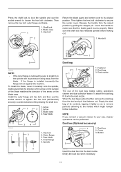
... the blade matches the direction of the dust bag makes cutting operations cleaner and dust collection easier. Dust box (Optional accessory) 1 1. Hex bolt 2. Spindle 009524 Dust bag 23 1 1 1. Hex bolt 3 009498 NOTE: • If the inner flange is installed incorrectly the flange will rub against the machine. Button 3 2 006793 Insert the dust box into the dust nozzle. Press the shaft lock to lock the spindle and use the socket wrench...
... the blade matches the direction of the dust bag makes cutting operations cleaner and dust collection easier. Dust box (Optional accessory) 1 1. Hex bolt 2. Spindle 009524 Dust bag 23 1 1 1. Hex bolt 3 009498 NOTE: • If the inner flange is installed incorrectly the flange will rub against the machine. Button 3 2 006793 Insert the dust box into the dust nozzle. Press the shaft lock to lock the spindle and use the socket wrench...
Owners Manual
Page 12
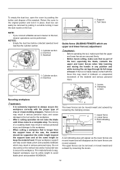
.... Turn base NOTE: • If you connect a Makita vacuum cleaner to the workpiece. • When cutting a workpiece that the upper and lower fences are moved inward and will help avoid blade pinch and possible kickback which may result in place. Clamping screws 2 010591 Securing workpiece WARNING: • It is longer than the support base of vise or crown molding stoppers. Lower fence 3. Dust box...
.... Turn base NOTE: • If you connect a Makita vacuum cleaner to the workpiece. • When cutting a workpiece that the upper and lower fences are moved inward and will help avoid blade pinch and possible kickback which may result in place. Clamping screws 2 010591 Securing workpiece WARNING: • It is longer than the support base of vise or crown molding stoppers. Lower fence 3. Dust box...
Owners Manual
Page 13
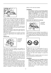
... lowest position. Turning the vise knob to 90° counterclockwise allows the vise knob to be installed in the base. Screw setting, turn base. Press the workpiece flat against the turn the vise knob clockwise to secure the workpiece. 009611 In case of bevel-cutting, adjust the lower and upper fence positions to be as close to the blade as practical to provide maximum workpiece support, and make...
... lowest position. Turning the vise knob to 90° counterclockwise allows the vise knob to be installed in the base. Screw setting, turn base. Press the workpiece flat against the turn the vise knob clockwise to secure the workpiece. 009611 In case of bevel-cutting, adjust the lower and upper fence positions to be as close to the blade as practical to provide maximum workpiece support, and make...
Owners Manual
Page 14
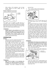
.... When the cut is completed, switch off the tool and WAIT UNTIL THE BLADE HAS COME TO A COMPLETE STOP before the switch is turned on. Screw personal injury. 1. Too much force as base boards, against the fence, always use , be cut in overload of vise or crown molding stoppers. WARNING: • Make sure the blade is applied, the blade will vibrate and leave a mark (saw mark) in...
.... When the cut is completed, switch off the tool and WAIT UNTIL THE BLADE HAS COME TO A COMPLETE STOP before the switch is turned on. Screw personal injury. 1. Too much force as base boards, against the fence, always use , be cut in overload of vise or crown molding stoppers. WARNING: • Make sure the blade is applied, the blade will vibrate and leave a mark (saw mark) in...
Owners Manual
Page 15
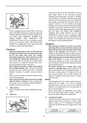
... pulled fully toward the guide fence. When the cut on a workpiece. Bevel cut Loosen the lever and tilt the saw blade to set the bevel angle (Refer to the turn base or if the pressure direction is being cut is applied perpendicularly to the previously covered "Adjusting the bevel angle"). Be sure to retighten the lever firmly to perform a slide cut keep hands out of the path of the blade may result in serious...
... pulled fully toward the guide fence. When the cut on a workpiece. Bevel cut Loosen the lever and tilt the saw blade to set the bevel angle (Refer to the turn base or if the pressure direction is being cut is applied perpendicularly to the previously covered "Adjusting the bevel angle"). Be sure to retighten the lever firmly to perform a slide cut keep hands out of the path of the blade may result in serious...
Owners Manual
Page 21
... cutting. Turn the turn base. Miter angle Push the carriage toward the guide fence and tighten the locking screw clockwise and pull the lock lever towards the front of the guide fence using the socket wrench. Carrying tool 1 1. The use gasoline, benzine, thinner, alcohol or the like. If you remove the holders, dust bag, etc., you can carry the tool more easily. 009506 WARNING: • Stopper pin is switched off the tool may result in accidental start...
... cutting. Turn the turn base. Miter angle Push the carriage toward the guide fence and tighten the locking screw clockwise and pull the lock lever towards the front of the guide fence using the socket wrench. Carrying tool 1 1. The use gasoline, benzine, thinner, alcohol or the like. If you remove the holders, dust bag, etc., you can carry the tool more easily. 009506 WARNING: • Stopper pin is switched off the tool may result in accidental start...
Owners Manual
Page 23
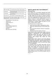
... laser line position For model LS1016L only 1. Turn these two screws clockwise to shift it on the turn on the laser unit. 23 Saw blade 009514 1. Screw to the side surface of the saw blade is. (Decide which position to the section titled "Laser line action" and adjust the adjusting screw so that the tool is changed by a Makita authorized service center for accuracy . • Have the tool repaired by turning two screws...
... laser line position For model LS1016L only 1. Turn these two screws clockwise to shift it on the turn on the laser unit. 23 Saw blade 009514 1. Screw to the side surface of the saw blade is. (Decide which position to the section titled "Laser line action" and adjust the adjusting screw so that the tool is changed by a Makita authorized service center for accuracy . • Have the tool repaired by turning two screws...
Owners Manual
Page 24
... replacing brushes, plug in the tool and break in brushes by running and electric brake operation when releasing the switch trigger. Keep the blade guard clean according to slip in such a way that the slide pole is thoroughly inserted into the turn base. The use of an accessory or attachment may result in serious personal injury. Screwdriver 1 2. Lens for the laser light 1 009610 To remove the lens for the laser light, remove the saw blade before removing...
... replacing brushes, plug in the tool and break in brushes by running and electric brake operation when releasing the switch trigger. Keep the blade guard clean according to slip in such a way that the slide pole is thoroughly inserted into the turn base. The use of an accessory or attachment may result in serious personal injury. Screwdriver 1 2. Lens for the laser light 1 009610 To remove the lens for the laser light, remove the saw blade before removing...
Owners Manual
Page 25
... TERM OF THIS WARRANTY. This Warranty gives you specific legal rights, and you may also have other non-ferrous metals. 006526 • Vise assembly (Horizontal vise) • Vertical vise • Socket wrench 13 • Holder • Dust bag • Crown molding stopper set • Triangular rule • Dust box • Hex wrench (for LS1016L) MAKITA LIMITED ONE YEAR WARRANTY Warranty Policy Every Makita tool is thoroughly inspected...
... TERM OF THIS WARRANTY. This Warranty gives you specific legal rights, and you may also have other non-ferrous metals. 006526 • Vise assembly (Horizontal vise) • Vertical vise • Socket wrench 13 • Holder • Dust bag • Crown molding stopper set • Triangular rule • Dust box • Hex wrench (for LS1016L) MAKITA LIMITED ONE YEAR WARRANTY Warranty Policy Every Makita tool is thoroughly inspected...

Parts Breakdown
Page 9
... 6 LEVER 22 PAN HEAD SCREW M4X10 COMPRESSION SPRING 6 LOCK PIN 8 LEAF SPRING CENTER SHAFT POSITION PLATE ARM HOLDER COVER TAPPING SCREW CT 4X16 SQUARE ROD COMPLETE RUBBER PIN 6 HEX.BOLT M5X30 TAPPING SCREW BIND CT 4X12 KURF BOARD HEX BOLT M8X45 FLAT WASHER 8 TURN BASE COMPLETE INDICATION LABEL INC. 244 TAPPING SCREW BIND CT 4X12 INDICATION PLATE RACK BLOCK TAPPING SCREW 4X14 FLAT WASHER 4 TAPPING SCREW BIND CT 4X12 SLIDE LOCK PLATE CAP STOP RING...
... 6 LEVER 22 PAN HEAD SCREW M4X10 COMPRESSION SPRING 6 LOCK PIN 8 LEAF SPRING CENTER SHAFT POSITION PLATE ARM HOLDER COVER TAPPING SCREW CT 4X16 SQUARE ROD COMPLETE RUBBER PIN 6 HEX.BOLT M5X30 TAPPING SCREW BIND CT 4X12 KURF BOARD HEX BOLT M8X45 FLAT WASHER 8 TURN BASE COMPLETE INDICATION LABEL INC. 244 TAPPING SCREW BIND CT 4X12 INDICATION PLATE RACK BLOCK TAPPING SCREW 4X14 FLAT WASHER 4 TAPPING SCREW BIND CT 4X12 SLIDE LOCK PLATE CAP STOP RING...

Flyer (English)
Page 2
... models and accessories subject to stock on its class for easy jobsite portability I Powerful 15 AMP direct drive motor requires less maintenance, and delivers 3,200 RPM with soft start for smoother power-ups I Electronic Speed Control maintains constant speed under load for smoother, higher-quality cutting I Exclusive 4-3/4" dual sliding fence system features upper and lower fence adjustments for more information, call 1-800-4MAKITA. For a complete listing, please refer to the Makita...
... models and accessories subject to stock on its class for easy jobsite portability I Powerful 15 AMP direct drive motor requires less maintenance, and delivers 3,200 RPM with soft start for smoother power-ups I Electronic Speed Control maintains constant speed under load for smoother, higher-quality cutting I Exclusive 4-3/4" dual sliding fence system features upper and lower fence adjustments for more information, call 1-800-4MAKITA. For a complete listing, please refer to the Makita...


