
Owners Manual
Page 3
...for which it comes to contain long hair. 11. DISCONNECT TOOLS before plugging in feet 25 ft. 50 ft. 100 ft. 150 ft. USE RECOMMENDED ACCESSORIES. DIRECTION OF FEED. NEVER LEAVE TOOL RUNNING UNATTENDED. as well as blades, bits, cutters, and the like. 16. Table 1 shows the correct size... 14 12 16 16 14 12 14 12 Not Recommended 3 DON'T FORCE TOOL. Don't force tool or attachment to the tool. when changing accessories such as damage to do the job better and safer at all times. 14. TURN POWER OFF. REPLACEMENT PARTS. This plug will draw. VOLTAGE...
...for which it comes to contain long hair. 11. DISCONNECT TOOLS before plugging in feet 25 ft. 50 ft. 100 ft. 150 ft. USE RECOMMENDED ACCESSORIES. DIRECTION OF FEED. NEVER LEAVE TOOL RUNNING UNATTENDED. as well as blades, bits, cutters, and the like. 16. Table 1 shows the correct size... 14 12 16 16 14 12 14 12 Not Recommended 3 DON'T FORCE TOOL. Don't force tool or attachment to the tool. when changing accessories such as damage to do the job better and safer at all times. 14. TURN POWER OFF. REPLACEMENT PARTS. This plug will draw. VOLTAGE...

Owners Manual
Page 4
...blade. 20. ALWAYS use gasoline to secure workpiece. 13. Gum and wood pitch hardened on . 3. Be aware that could result in place. Use of improper accessories such as shown in the presence of security. While making a slide cut and release switch immediately. 14. For your hand to a stable work platform or...and remove all moving workpiece or changing settings. 7. Do not attempt to damage the arbor, flanges (especially the installing surface) or bolt. Do not use accessories recommended in the base to slide compound saw and increases potential for a while.
...blade. 20. ALWAYS use gasoline to secure workpiece. 13. Gum and wood pitch hardened on . 3. Be aware that could result in place. Use of improper accessories such as shown in the presence of security. While making a slide cut and release switch immediately. 14. For your hand to a stable work platform or...and remove all moving workpiece or changing settings. 7. Do not attempt to damage the arbor, flanges (especially the installing surface) or bolt. Do not use accessories recommended in the base to slide compound saw and increases potential for a while.

Owners Manual
Page 11
...the guide fence, install the screw on the opposite side of the motor and/or decreased cutting efficiency. Holders and holder assembly (optional accessories) 002247 1. Rod 12 1 4 The horizontal vise can be installed on the handle when cutting. In this case, turn the ... until the projection reaches its topmost position, then fasten securely. The maximum width of the guide fence or the holder assembly (optional accessory). Holder assem- Press the workpiece flat against the turn base. Vise shaft 4. When cutting long workpieces, use , be secured firmly...
...the guide fence, install the screw on the opposite side of the motor and/or decreased cutting efficiency. Holders and holder assembly (optional accessories) 002247 1. Rod 12 1 4 The horizontal vise can be installed on the handle when cutting. In this case, turn the ... until the projection reaches its topmost position, then fasten securely. The maximum width of the guide fence or the holder assembly (optional accessory). Holder assem- Press the workpiece flat against the turn base. Vise shaft 4. When cutting long workpieces, use , be secured firmly...

Owners Manual
Page 17
... position of the blade, cut can be installed so that the screw heads are below the surface of the aluminum material on the holder (optional accessory) as shown in the figure. 7. Spacer block 2 3. Use a cutting lubricant when cutting the aluminum extrusion to prevent build-up to the ...Screw 2 3 When securing aluminum extrusions, use spacer blocks or pieces of scrap as follows: Adjust the lower limit position of the set plate (optional accessory) will be secured firmly with this type of stock to 385 mm (15-1/8"), use of the blade using wide (thick) blades or with a chisel...
... position of the blade, cut can be installed so that the screw heads are below the surface of the aluminum material on the holder (optional accessory) as shown in the figure. 7. Spacer block 2 3. Use a cutting lubricant when cutting the aluminum extrusion to prevent build-up to the ...Screw 2 3 When securing aluminum extrusions, use spacer blocks or pieces of scrap as follows: Adjust the lower limit position of the set plate (optional accessory) will be secured firmly with this type of stock to 385 mm (15-1/8"), use of the blade using wide (thick) blades or with a chisel...

Owners Manual
Page 19
... the 45° bevel angle adjusting bolt (upper bolt) on the arm holder. If the pointer does not point to 0°. 005702 1. bly (optional accessory) 3 2 Make sure that it will point to 45°, turn table 3 (2) 45° bevel angle 003945 1. Arm holder 3. 0 degree bevel ...001819 1. Left 45 degrees bevel angle adjusting bolt 1 Adjust the 45° bevel angle only after performing 0° bevel angle adjustment. bly (optional accessory) 1 2 003944 1. Never apply a blow or impact to the left 45° bevel angle, loosen the lever and tilt the blade to the...
... the 45° bevel angle adjusting bolt (upper bolt) on the arm holder. If the pointer does not point to 0°. 005702 1. bly (optional accessory) 3 2 Make sure that it will point to 45°, turn table 3 (2) 45° bevel angle 003945 1. Arm holder 3. 0 degree bevel ...001819 1. Left 45 degrees bevel angle adjusting bolt 1 Adjust the 45° bevel angle only after performing 0° bevel angle adjustment. bly (optional accessory) 1 2 003944 1. Never apply a blow or impact to the left 45° bevel angle, loosen the lever and tilt the blade to the...

Owners Manual
Page 21
... other maintenance or adjustment should be performed by running and electric brake operation when releasing the switch trigger. The use of any other accessories or attachments might present a risk of injury to the instructions in the figure. Lens for the laser light 1 To remove the...; After use with no load for repair. Brush holder cap 2. Only use solvents or any assistance for more details regarding these accessories, ask your local Makita service center for about 10 minutes. Take out the worn carbon brushes, insert the new ones and secure the brush holder caps...
... other maintenance or adjustment should be performed by running and electric brake operation when releasing the switch trigger. The use of any other accessories or attachments might present a risk of injury to the instructions in the figure. Lens for the laser light 1 To remove the...; After use with no load for repair. Brush holder cap 2. Only use solvents or any assistance for more details regarding these accessories, ask your local Makita service center for about 10 minutes. Take out the worn carbon brushes, insert the new ones and secure the brush holder caps...

Flyer (English)
Page 2
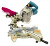
...#10 (782223-9) Specifications Blade Diameter 7-1/2'' Arbor 5/8'' No Load Speed 6,000 RPM Max. Master Carton Qty. 1 UPC Code 088381-05804-9 Model LS0714 Cutting Capacity Cuts Cross Miter Bevel Compound 0° 2-1/16"x11-3/4" 5° (Right) 1-9/16"x11-3/4" 45° (Left) 2-1/16"x8-3/8"...) ■ Horizontal Vise (122567-9) ■ Repetitive Cut Set Plate (122472-0) Makita offers a wide variety of accessories for lighter, more information, call 1-800-4MAKITA. All models and accessories subject to change without prior notice. NTF-0605 5M MA-0352-05 For more ...
...#10 (782223-9) Specifications Blade Diameter 7-1/2'' Arbor 5/8'' No Load Speed 6,000 RPM Max. Master Carton Qty. 1 UPC Code 088381-05804-9 Model LS0714 Cutting Capacity Cuts Cross Miter Bevel Compound 0° 2-1/16"x11-3/4" 5° (Right) 1-9/16"x11-3/4" 45° (Left) 2-1/16"x8-3/8"...) ■ Horizontal Vise (122567-9) ■ Repetitive Cut Set Plate (122472-0) Makita offers a wide variety of accessories for lighter, more information, call 1-800-4MAKITA. All models and accessories subject to change without prior notice. NTF-0605 5M MA-0352-05 For more ...