Owners Manual
Page 1
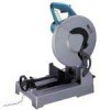
A A. A A.. WARNING: For your personal safety, READ and UNDERSTAND before using. B --b- SAVE THESE INSTRUCTIONS FOR FUTURE REFERENCE. Metal Cutting Saw 305 mm (12") MODEL LC1230 INSTRUCTION MANUAL O a DOUBLE INSULATION SPECIFICATIONS Blade diameter Hole (arbor) diameter No load speed (RPM) Dimensions (L x W x Hl Net weight Cutting capacity Workpiece shape 305 mm (12") 25.4 mm (1") 1 300 516...
A A. A A.. WARNING: For your personal safety, READ and UNDERSTAND before using. B --b- SAVE THESE INSTRUCTIONS FOR FUTURE REFERENCE. Metal Cutting Saw 305 mm (12") MODEL LC1230 INSTRUCTION MANUAL O a DOUBLE INSULATION SPECIFICATIONS Blade diameter Hole (arbor) diameter No load speed (RPM) Dimensions (L x W x Hl Net weight Cutting capacity Workpiece shape 305 mm (12") 25.4 mm (1") 1 300 516...
Owners Manual
Page 3
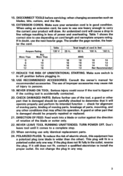
...the plug. REDUCE THE RISK OF UNINTENTIONAL STARTING. Consult the owner's manual for alignment of moving parts, binding of moving parts, breakage of the blade or cutter only. 22. TURN POWER OFF. To reduce the risk of power and overheating. An undersized cord will draw. USE RECOMMENDED ACCESSORIES....should be carefully checked to determine that is damaged should be sure to install the proper outlet. DIRECTION OF FEED. Feed work into a blade or cutter against the direction of rotation of parts, mounting, and any way. 3 If the plug does not fit fully in feet Ampere...
...the plug. REDUCE THE RISK OF UNINTENTIONAL STARTING. Consult the owner's manual for alignment of moving parts, binding of moving parts, breakage of the blade or cutter only. 22. TURN POWER OFF. To reduce the risk of power and overheating. An undersized cord will draw. USE RECOMMENDED ACCESSORIES....should be carefully checked to determine that is damaged should be sure to install the proper outlet. DIRECTION OF FEED. Feed work into a blade or cutter against the direction of rotation of parts, mounting, and any way. 3 If the plug does not fit fully in feet Ampere...
Owners Manual
Page 4
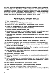
...any operation freehand. Be careful not to these parts could indicate poor installation or a poorly balanced blade. 17. For your safety, remove the chips, small pieces, etc. Make sure the blade is not contacting the workpiece before cutting. 18. Use only flanges specified for a while. Do ...not attempt to lock the trigger in blade breakage. 7. Wear eye protection. 2. Keep hands out of path of flammable liquids or gases. 4. Watch for cracks or damage before operation...
...any operation freehand. Be careful not to these parts could indicate poor installation or a poorly balanced blade. 17. For your safety, remove the chips, small pieces, etc. Make sure the blade is not contacting the workpiece before cutting. 18. Use only flanges specified for a while. Do ...not attempt to lock the trigger in blade breakage. 7. Wear eye protection. 2. Keep hands out of path of flammable liquids or gases. 4. Watch for cracks or damage before operation...
Owners Manual
Page 5
...Never yank cord to disconnect it from heat, oil, water and sharp edges. 25. Never attempt to cut off tool and wait for saw blade to the carbide-tips. 21. Unplug tool before moving workpiece or changing settings. 23. Be alert at all times, especially during repetitive, ...monotonous operations. Use of security. Don't abuse cord. Blades are extremely unforgiving. 22. The piece cut workpieces less than 14 Gauge (0.08") thick except pipe or workpieces which cannot be caught by the...
...Never yank cord to disconnect it from heat, oil, water and sharp edges. 25. Never attempt to cut off tool and wait for saw blade to the carbide-tips. 21. Unplug tool before moving workpiece or changing settings. 23. Be alert at all times, especially during repetitive, ...monotonous operations. Use of security. Don't abuse cord. Blades are extremely unforgiving. 22. The piece cut workpieces less than 14 Gauge (0.08") thick except pipe or workpieces which cannot be caught by the...
Owners Manual
Page 7
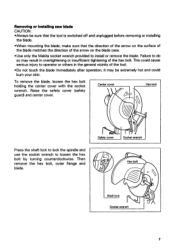
...of the hex bolt. it may result in the general vicinity of the tool. •Do not touch the blade immediately after operation; Removing or Installing saw blade CAUTION: •Always be extremely hot and could cause serious injury to operator or others in overtightening or insufficient ...tightening of the arrow on the blade case. •Use only the Makita socket wrench provided to install or remove the blade. Pro. Failure to loosen the hex bolt by turning counterclockwise. To remove the blade, loosen the hex bolt holding the center cover with ...
...of the hex bolt. it may result in the general vicinity of the tool. •Do not touch the blade immediately after operation; Removing or Installing saw blade CAUTION: •Always be extremely hot and could cause serious injury to operator or others in overtightening or insufficient ...tightening of the arrow on the blade case. •Use only the Makita socket wrench provided to install or remove the blade. Pro. Failure to loosen the hex bolt by turning counterclockwise. To remove the blade, loosen the hex bolt holding the center cover with ...
Owners Manual
Page 8
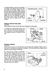
Then tighten the hex bolt clockwise to the original position. Carbide•tipped saw blade, outer flange and hex bolt onto the spindle in and out. Vise plate Vise nut Vise handle 0 8 Tighten the hex bolt by turning clockwise while ... lever to secure the vise stop Securing workplaces CAUTION: Always set the vise nut to the blade. Move the vise stop so that the safety cover moves properly. To install the blade, mount the inner flange, saw blade Hex bolt Spindle Inner flange 6 Outer flan e Setting for desired cutting angle CAUTION: Always tighten...
Then tighten the hex bolt clockwise to the original position. Carbide•tipped saw blade, outer flange and hex bolt onto the spindle in and out. Vise plate Vise nut Vise handle 0 8 Tighten the hex bolt by turning clockwise while ... lever to secure the vise stop Securing workplaces CAUTION: Always set the vise nut to the blade. Move the vise stop so that the safety cover moves properly. To install the blade, mount the inner flange, saw blade Hex bolt Spindle Inner flange 6 Outer flan e Setting for desired cutting angle CAUTION: Always tighten...
Owners Manual
Page 9
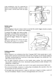
...the handle may result. •Do not apply excessive pressure on either side so that it in more sparks and premature blade wear. •Do not touch the blade, workpiece or cutting chips immediately after operation; Possible serious injury may result in a secure place. Handle Lock-off button... to see that the switch trigger actuates properly and returns to the "OFF" position when released. Long workpieces must be supported by the blade, causing dangerous scattering of chips and/or damage to the carbide-tips. To start the tool, press in the lock-off button Switch trigger...
...the handle may result. •Do not apply excessive pressure on either side so that it in more sparks and premature blade wear. •Do not touch the blade, workpiece or cutting chips immediately after operation; Possible serious injury may result in a secure place. Handle Lock-off button... to see that the switch trigger actuates properly and returns to the "OFF" position when released. Long workpieces must be supported by the blade, causing dangerous scattering of chips and/or damage to the carbide-tips. To start the tool, press in the lock-off button Switch trigger...
Owners Manual
Page 10
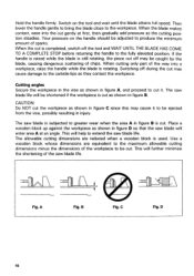
.... This will further minimize the shortening of the way into the cut the workpiece as shown in injury. If the handle is raised while the blade is used. Use a wooden block whose dimensions are reduced when a wooden block is still rotating, the piece cut as they contact the workpiece. B... to produce the minimum amount of chips. When the cut is cut it to be shortened if the workpiece is subjected to extend the saw blade life. This will enter area A at first, then gradually add pressure as shown in figure B is completed, switch off may cause it . A Fig. ...
.... This will further minimize the shortening of the way into the cut the workpiece as shown in injury. If the handle is raised while the blade is used. Use a wooden block whose dimensions are reduced when a wooden block is still rotating, the piece cut as they contact the workpiece. B... to produce the minimum amount of chips. When the cut is cut it to be shortened if the workpiece is subjected to extend the saw blade life. This will enter area A at first, then gradually add pressure as shown in figure B is completed, switch off may cause it . A Fig. ...
Owners Manual
Page 11
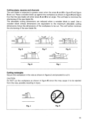
...is subjected to greater wear when the areas A and B in figure F and figure G are cut . This will further minimize the shortening of the saw blade life. G Fig. J Fig. K 11 Place a wooden block up against the workpiece as shown in figure H and figure I Cutting rectangles Secure the workpiece... figure K since this may cause it . Use a wooden block whose dimensions are equivalent to the maximum allowable cutting dimensions minus the dimensions of the saw blade life. Fig. F 11 1 1 11111 H Fig. CAUTION: Do NOT cut it to be cut . This will enter areas A and B at an angle. ...
...is subjected to greater wear when the areas A and B in figure F and figure G are cut . This will further minimize the shortening of the saw blade life. G Fig. J Fig. K 11 Place a wooden block up against the workpiece as shown in figure H and figure I Cutting rectangles Secure the workpiece... figure K since this may cause it . Use a wooden block whose dimensions are equivalent to the maximum allowable cutting dimensions minus the dimensions of the saw blade life. Fig. F 11 1 1 11111 H Fig. CAUTION: Do NOT cut it to be cut . This will enter areas A and B at an angle. ...
Owners Manual
Page 13
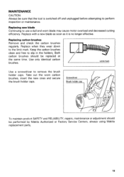
...caps. Limit mark Use a screwdriver to slip in the holders. Replace when they wear down to use a dull and worn blade may cause motor overload and decreased cutting efficiency. Screwdriver Brush holder cap 0 To maintain product SAFETY and RELIABILITY, repairs, maintenance... or adjustment should be performed by Makita Authorized or Factory Service Centers, always using Makita replacement parts,. 13 Replacing carbon brushes Remove and check the carbon brushes regularly. Both carbon brushes should...
...caps. Limit mark Use a screwdriver to slip in the holders. Replace when they wear down to use a dull and worn blade may cause motor overload and decreased cutting efficiency. Screwdriver Brush holder cap 0 To maintain product SAFETY and RELIABILITY, repairs, maintenance... or adjustment should be performed by Makita Authorized or Factory Service Centers, always using Makita replacement parts,. 13 Replacing carbon brushes Remove and check the carbon brushes regularly. Both carbon brushes should...
Owners Manual
Page 14
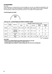
... CAUTION: • Always use carbide-tipped saw blades appropriate for your Makita tool specified in the proper and intended manner. •Carbide-tipped saw blade r. 305 mm (12") Carbide-tipped saw are recommended for metal cutting saw blade & workpiece ranges Part No. The use with your...attachments should be re-sharpened. 14 Do not cut aluminum, wood, plastics, concrete, tiles, etc. • Carbide-tipped saw blades for use of any other accessories or attachments might present a risk of teeth Application Angles Applicable workpiece & thickness range Pipes Channels ...
... CAUTION: • Always use carbide-tipped saw blades appropriate for your Makita tool specified in the proper and intended manner. •Carbide-tipped saw blade r. 305 mm (12") Carbide-tipped saw are recommended for metal cutting saw blade & workpiece ranges Part No. The use with your...attachments should be re-sharpened. 14 Do not cut aluminum, wood, plastics, concrete, tiles, etc. • Carbide-tipped saw blades for use of any other accessories or attachments might present a risk of teeth Application Angles Applicable workpiece & thickness range Pipes Channels ...
Owners Manual
Page 17
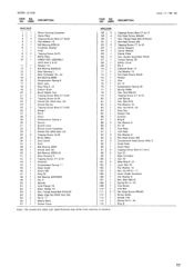
... 3-16 Vise Screw Vise Nut Paid Head Screw M8x30 Screw Guide Handle 100 Spring Pin 5-24 Ring 8 17 Flange Heed Bolt M10x20 Blade Case Set With Item 561 Pin 6-7' Makita Mark Center Cover MACHINE 58 2 59 4 60 1 61 1 62 2 63 I 64 1 65 1 66 67 12 68 1 69 1 70 71 72 ... Cap 20 Base Complete Cap 16 Stop Ring E-8 Lever Rod 10 Flat Washer 10 Hex. Bolt M8x20 Tapping Screw CT 4x16 Leal Spring Hex. MODEL LC1230 ITEM NO. USED DESCRIPTION June -7-'99 US MACHINE 1 1 2 1 3 4 5 1 6 1 7 9 10 11 12 13 1 14 1 15 16 1 17 1 18 19 2 20 2 21 22 4 23...
... 3-16 Vise Screw Vise Nut Paid Head Screw M8x30 Screw Guide Handle 100 Spring Pin 5-24 Ring 8 17 Flange Heed Bolt M10x20 Blade Case Set With Item 561 Pin 6-7' Makita Mark Center Cover MACHINE 58 2 59 4 60 1 61 1 62 2 63 I 64 1 65 1 66 67 12 68 1 69 1 70 71 72 ... Cap 20 Base Complete Cap 16 Stop Ring E-8 Lever Rod 10 Flat Washer 10 Hex. Bolt M8x20 Tapping Screw CT 4x16 Leal Spring Hex. MODEL LC1230 ITEM NO. USED DESCRIPTION June -7-'99 US MACHINE 1 1 2 1 3 4 5 1 6 1 7 9 10 11 12 13 1 14 1 15 16 1 17 1 18 19 2 20 2 21 22 4 23...
Parts Breakdown
Page 3
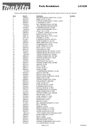
... B. SCREW M6X60, LS1030 Page 3 of 4 Quantity 1 1 4 1 1 1 1 1 1 2 1 1 1 1 1 1 1 1 1 1 1 1 2 1 4 1 1 2 1 1 1 1 1 1 1 1 1 2 1 1 1 1 1 1 1 2 1 1 1 1 1 1 1 1 1 1 1 1 1 2 1 1 2 4 8/18/2010 SPRING 11, 2040 BLADE GUIDE, LC1230 SCREW M6, LC1230 RING 20, LC1230 BALL BEARING 6204DDW, LC1230 KEY 5, HR4000C SPINDLE, LC1230 INNER FLANGE 70, LC1230 OUTER FLANGE 70, LC1230 OUTER FLANGE 69 LC1230 HEX FLANGE H.BOLT M10X20,LC1230 BLADE CASE SET, LC1230 PIN 6-7, 4303C MAKITA MARK, 5402NA CENTER COVER, LC1230 TAPPING SCREW BIND CT5X12, 9031 P.H. Parts Breakdown...
... B. SCREW M6X60, LS1030 Page 3 of 4 Quantity 1 1 4 1 1 1 1 1 1 2 1 1 1 1 1 1 1 1 1 1 1 1 2 1 4 1 1 2 1 1 1 1 1 1 1 1 1 2 1 1 1 1 1 1 1 2 1 1 1 1 1 1 1 1 1 1 1 1 1 2 1 1 2 4 8/18/2010 SPRING 11, 2040 BLADE GUIDE, LC1230 SCREW M6, LC1230 RING 20, LC1230 BALL BEARING 6204DDW, LC1230 KEY 5, HR4000C SPINDLE, LC1230 INNER FLANGE 70, LC1230 OUTER FLANGE 70, LC1230 OUTER FLANGE 69 LC1230 HEX FLANGE H.BOLT M10X20,LC1230 BLADE CASE SET, LC1230 PIN 6-7, 4303C MAKITA MARK, 5402NA CENTER COVER, LC1230 TAPPING SCREW BIND CT5X12, 9031 P.H. Parts Breakdown...
Parts Breakdown
Page 4
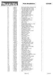
... PIN 5-24, HR5210C RING 8, LS1020, M242, (T2) SOCKET WRENCH 17,2414B SAFETY GOGGLES 12C.T.BLADE,60T,LC1230 12 C.T.BLADE, 60T,LC1230,T1 SWITCH BUTTON, LS1011 N/A Page 4 of 4 LC1230 1 1 1 2 1 1 1 2 1 1 1 1 1 1 1 1 1 1 1 1 1 1 1 1 1 1 1 1 1 2 1 1 1 2 2 2 2 3 1 1 3 5 1 1 2 1 1 1 1 1 1 1 1 1 2 1 1 1 1 1 1 1 1 1 2 1 8/18/2010 WASHER 10, LS0714 HEX NUT M10-17, LC1230 LEVER HOLDER COMPLETE, LC1230 F. 60 61 61 62 63 64 65 66 67 68 69 70 71 72 73...
... PIN 5-24, HR5210C RING 8, LS1020, M242, (T2) SOCKET WRENCH 17,2414B SAFETY GOGGLES 12C.T.BLADE,60T,LC1230 12 C.T.BLADE, 60T,LC1230,T1 SWITCH BUTTON, LS1011 N/A Page 4 of 4 LC1230 1 1 1 2 1 1 1 2 1 1 1 1 1 1 1 1 1 1 1 1 1 1 1 1 1 1 1 1 1 2 1 1 1 2 2 2 2 3 1 1 3 5 1 1 2 1 1 1 1 1 1 1 1 1 2 1 1 1 1 1 1 1 1 1 2 1 8/18/2010 WASHER 10, LS0714 HEX NUT M10-17, LC1230 LEVER HOLDER COMPLETE, LC1230 F. 60 61 61 62 63 64 65 66 67 68 69 70 71 72 73...


