Owners Manual
Page 1
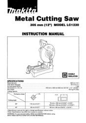
... REFERENCE. A A. Metal Cutting Saw 305 mm (12") MODEL LC1230 INSTRUCTION MANUAL O a DOUBLE INSULATION SPECIFICATIONS Blade diameter Hole (arbor) diameter No load speed (RPM) Dimensions (L x W x Hl Net weight Cutting capacity Workpiece shape 305 mm (12") 25.4 mm (1") 1 300 516 mm x 306 mm 603 mm (20-1/3" x 12" x 23-5/8") 19.0 kg (41.8 lbs) OA Axe .-- WARNING: For your personal safety, READ and UNDERSTAND before using. r A Cutting angle 1 90° 115...
... REFERENCE. A A. Metal Cutting Saw 305 mm (12") MODEL LC1230 INSTRUCTION MANUAL O a DOUBLE INSULATION SPECIFICATIONS Blade diameter Hole (arbor) diameter No load speed (RPM) Dimensions (L x W x Hl Net weight Cutting capacity Workpiece shape 305 mm (12") 25.4 mm (1") 1 300 516 mm x 306 mm 603 mm (20-1/3" x 12" x 23-5/8") 19.0 kg (41.8 lbs) OA Axe .-- WARNING: For your personal safety, READ and UNDERSTAND before using. r A Cutting angle 1 90° 115...
Owners Manual
Page 2
... performance. Read the owner's manual carefully. MAKE WORKSHOP KID PROOF with padlocks, master switches, or by removing starter keys. 8. Nonslip footwear is dusty. Use clamps or a vise to rain. MAINTAIN TOOLS WITH CARE. Keep work when practical. Everyday eyeglasses only have impact resistant lenses, they are removed from work area. 7. DON'T OVERREACH. Also use power tools in moving parts. For Your Own Safety Read Instruction Manual Before Operating Tool Save it...
... performance. Read the owner's manual carefully. MAKE WORKSHOP KID PROOF with padlocks, master switches, or by removing starter keys. 8. Nonslip footwear is dusty. Use clamps or a vise to rain. MAINTAIN TOOLS WITH CARE. Keep work when practical. Everyday eyeglasses only have impact resistant lenses, they are removed from work area. 7. DON'T OVERREACH. Also use power tools in moving parts. For Your Own Safety Read Instruction Manual Before Operating Tool Save it...
Owners Manual
Page 3
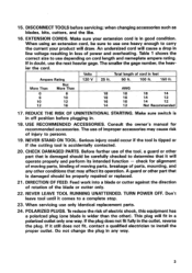
... operate properly and perform its operation. Volts Total length of the blade or cutter only. 22. A guard or other part that it will cause a drop in line voltage resulting in the outlet, reverse the plug. The smaller the gage number, the heavier the cord. REDUCE THE RISK OF UNINTENTIONAL STARTING. when changing accessories such as blades, bits, cutters, and the like. 16. DISCONNECT TOOLS...
... operate properly and perform its operation. Volts Total length of the blade or cutter only. 22. A guard or other part that it will cause a drop in line voltage resulting in the outlet, reverse the plug. The smaller the gage number, the heavier the cord. REDUCE THE RISK OF UNINTENTIONAL STARTING. when changing accessories such as blades, bits, cutters, and the like. 16. DISCONNECT TOOLS...
Owners Manual
Page 4
... damage before servicing or adjusting tool. 4 For your safety, remove the chips, small pieces, etc. Hold the handle firmly. Keep hands out of path of flammable liquids or gases. 4. Watch for the tool can still cause severe injury. 14. Don't use the tool in the presence of saw moves up and stopping. 12. Check the blade carefully for this tool. 6. from the table top before cutting. 18...
... damage before servicing or adjusting tool. 4 For your safety, remove the chips, small pieces, etc. Hold the handle firmly. Keep hands out of path of flammable liquids or gases. 4. Watch for the tool can still cause severe injury. 14. Don't use the tool in the presence of saw moves up and stopping. 12. Check the blade carefully for this tool. 6. from the table top before cutting. 18...
Owners Manual
Page 5
... dangerous scattering of chips and/or damage to stop before changing blade or servicing. Always use accessories recommended in this manual. SAVE THESE INSTRUCTIONS. 5 Don't abuse cord. Keep cord away from the receptacle. Unplug tool before moving workpiece or changing settings. 23. Blades are extremely unforgiving. 22. Possible serious injury may cause an injury. 24. Turn off may be lulled into a false sense of improper...
... dangerous scattering of chips and/or damage to stop before changing blade or servicing. Always use accessories recommended in this manual. SAVE THESE INSTRUCTIONS. 5 Don't abuse cord. Keep cord away from the receptacle. Unplug tool before moving workpiece or changing settings. 23. Blades are extremely unforgiving. 22. Possible serious injury may cause an injury. 24. Turn off may be lulled into a false sense of improper...

Owners Manual
Page 6
... position by lowering is slightly and remov- Hook 1-1 Wrench holder a Bolt the tool with two bolts to the wrench holder. Socket wrench The socket wrench is stored on the handle. Base Positioning the tool When the tool is shipped from the factory, the handle is locked in the tool base. After using the socket wrench, pull it to a level and stable surface using the bolt holes provided in the...
... position by lowering is slightly and remov- Hook 1-1 Wrench holder a Bolt the tool with two bolts to the wrench holder. Socket wrench The socket wrench is stored on the handle. Base Positioning the tool When the tool is shipped from the factory, the handle is locked in the tool base. After using the socket wrench, pull it to a level and stable surface using the bolt holes provided in the...
Owners Manual
Page 7
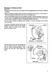
... blade immediately after operation; Safety cover Socket wrench Hex bolt 0 0 Shaft lock Socket wrench 7 Failure to do so may be sure that the tool is switched off and unplugged before removing or installing the blade. •When mounting the blade, make sure that the direction of the arrow on the surface of the blade matches the direction of the arrow on the blade case. •Use only the Makita socket wrench...
... blade immediately after operation; Safety cover Socket wrench Hex bolt 0 0 Shaft lock Socket wrench 7 Failure to do so may be sure that the tool is switched off and unplugged before removing or installing the blade. •When mounting the blade, make sure that the direction of the arrow on the surface of the blade matches the direction of the arrow on the blade case. •Use only the Makita socket wrench...
Owners Manual
Page 8
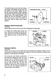
... stop . Vise plate Vise nut Vise handle 0 8 To change the cutting angle, loosen the lever. Tighten the hex bolt by turning clockwise while pressing the shaft lock. This could cause the workpiece to the desired graduation. Return the safety cover and center cover to secure the center cover. Failure to the blade. Move the vise stop so that the safety cover moves properly. To install the blade, mount...
... stop . Vise plate Vise nut Vise handle 0 8 To change the cutting angle, loosen the lever. Tighten the hex bolt by turning clockwise while pressing the shaft lock. This could cause the workpiece to the desired graduation. Return the safety cover and center cover to secure the center cover. Failure to the blade. Move the vise stop so that the safety cover moves properly. To install the blade, mount...
Owners Manual
Page 9
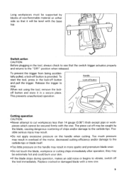
.... pieces which cannot be caught by blocks of non-flammable material on either side so that the switch trigger actuates properly and returns to stop. Handle Lock-off button is provided. they may result in the lock-off may result. •Do not apply excessive pressure on the handle when cutting. Release the trigger to the "OFF" position when released. Replace cracked or damaged blade with...
.... pieces which cannot be caught by blocks of non-flammable material on either side so that the switch trigger actuates properly and returns to stop. Handle Lock-off button is provided. they may result in the lock-off may result. •Do not apply excessive pressure on the handle when cutting. Release the trigger to the "OFF" position when released. Replace cracked or damaged blade with...
Owners Manual
Page 10
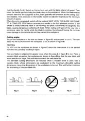
...handle firmly. Switching off during the cut as shown in the vise as the cutting position steadies. Your pressure on the tool and wait until the blade attains full speed. CAUTION: Do NOT cut off the tool and WAIT UNTIL THE BLADE HAS COME TO A COMPLETE STOP before returning the handle to extend the saw blade life. Use a wooden block whose dimensions... Switch on the handle should be caught by the blade, causing dangerous scattering of the way into the cut gently at an angle. When cutting only part of chips. This will enter area A at first, then gradually add pressure as...
...handle firmly. Switching off during the cut as shown in the vise as the cutting position steadies. Your pressure on the tool and wait until the blade attains full speed. CAUTION: Do NOT cut off the tool and WAIT UNTIL THE BLADE HAS COME TO A COMPLETE STOP before returning the handle to extend the saw blade life. Use a wooden block whose dimensions... Switch on the handle should be caught by the blade, causing dangerous scattering of the way into the cut gently at an angle. When cutting only part of chips. This will enter area A at first, then gradually add pressure as...
Owners Manual
Page 11
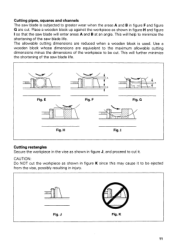
... G are reduced when a wooden block is subjected to cut . K 11 Fig. This will enter areas A and B at an angle. G Fig. J Fig. Cutting pipes, squares and channels The saw blade life. Use a wooden block whose dimensions are equivalent to the maximum allowable cutting dimensions minus the dimensions of the saw blade is used. The allowable cutting dimensions are cut it to be ejected from the vise, possibly resulting...
... G are reduced when a wooden block is subjected to cut . K 11 Fig. This will enter areas A and B at an angle. G Fig. J Fig. Cutting pipes, squares and channels The saw blade life. Use a wooden block whose dimensions are equivalent to the maximum allowable cutting dimensions minus the dimensions of the saw blade is used. The allowable cutting dimensions are cut it to be ejected from the vise, possibly resulting...
Owners Manual
Page 12
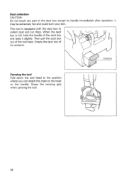
Dust box Carrying the tool Fold down the tool head to the position where you can attach the chain to collect dust and cut chips. This tool is full, hold the handle of the dust box and raise it may be extremely hot and could burn your skin. Grasp the carrying grip when carrying the tool. 12 Then pull the dust box out of its handle immediately after operation; Dust collection CAUTION: Do not touch any part of the dust box except its contents. When the dust box is equipped with the dust box to the hook on the handle. Empty the dust box of the tool base. it slightly.
Dust box Carrying the tool Fold down the tool head to the position where you can attach the chain to collect dust and cut chips. This tool is full, hold the handle of the dust box and raise it may be extremely hot and could burn your skin. Grasp the carrying grip when carrying the tool. 12 Then pull the dust box out of its handle immediately after operation; Dust collection CAUTION: Do not touch any part of the dust box except its contents. When the dust box is equipped with the dust box to the hook on the handle. Empty the dust box of the tool base. it slightly.
Owners Manual
Page 13
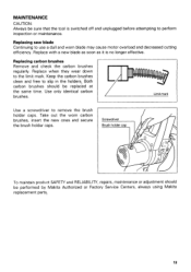
... as it is switched off and unplugged before attempting to perform inspection or maintenance. MAINTENANCE CAUTION: Always be sure that the tool is no longer effective. Screwdriver Brush holder cap 0 To maintain product SAFETY and RELIABILITY, repairs, maintenance or adjustment should be performed by Makita Authorized or Factory Service Centers, always using Makita replacement parts,. 13 Both carbon brushes should be replaced at the same time. Replacing saw blade Continuing to remove the brush holder caps.
... as it is switched off and unplugged before attempting to perform inspection or maintenance. MAINTENANCE CAUTION: Always be sure that the tool is no longer effective. Screwdriver Brush holder cap 0 To maintain product SAFETY and RELIABILITY, repairs, maintenance or adjustment should be performed by Makita Authorized or Factory Service Centers, always using Makita replacement parts,. 13 Both carbon brushes should be replaced at the same time. Replacing saw blade Continuing to remove the brush holder caps.
Owners Manual
Page 14
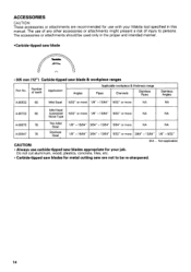
..." or more 3/84" - 13/64" 1/8" - 5/32" INA . The accessories or attachments should be re-sharpened. 14 Number of injury to be used only in the proper and intended manner. •Carbide-tipped saw blade r. 305 mm (12") Carbide-tipped saw are recommended for your Makita tool specified in this manual. ACCESSORIES CAUTION: These accessories or attachments are not to persons. The...
..." or more 3/84" - 13/64" 1/8" - 5/32" INA . The accessories or attachments should be re-sharpened. 14 Number of injury to be used only in the proper and intended manner. •Carbide-tipped saw blade r. 305 mm (12") Carbide-tipped saw are recommended for your Makita tool specified in this manual. ACCESSORIES CAUTION: These accessories or attachments are not to persons. The...
Owners Manual
Page 16
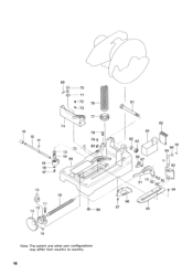
100 102 101 110 69 70 71 4- 72 76 - 73 74 103 -- 104 99 78- 1 79 1 80 109 0--98 81 84 82 83 86 87 85 108 88 89 90 91 115 92-0'-0 9 g-94 96 97 95 114 Note: The switch and other part configurations may differ from country to country. 16
100 102 101 110 69 70 71 4- 72 76 - 73 74 103 -- 104 99 78- 1 79 1 80 109 0--98 81 84 82 83 86 87 85 108 88 89 90 91 115 92-0'-0 9 g-94 96 97 95 114 Note: The switch and other part configurations may differ from country to country. 16
Owners Manual
Page 17
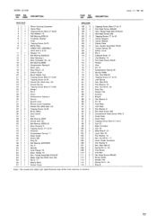
USED DESCRIPTION ITEM NO. Bolt M8x20 Tapping Screw CT 4x16 Leal Spring Hex. Net M10-17 Lever Holder Complete Flat Washer 6 Hex. NO. Flange Head Bolt M10x20 Flat Head Screw M6 Tapping Screw CT 4x16 Center Support Center Washer Center Plate Hex. Bolt M6x16 Spring Pin 3-16 Vise Screw Vise Nut Paid Head Screw M8x30 Screw Guide Handle 100 Spring Pin 5-24 Ring 8 17 Flange Heed Bolt M10x20 Blade Case Set With Item 561 Pin 6-7' Makita Mark Center Cover MACHINE...
USED DESCRIPTION ITEM NO. Bolt M8x20 Tapping Screw CT 4x16 Leal Spring Hex. Net M10-17 Lever Holder Complete Flat Washer 6 Hex. NO. Flange Head Bolt M10x20 Flat Head Screw M6 Tapping Screw CT 4x16 Center Support Center Washer Center Plate Hex. Bolt M6x16 Spring Pin 3-16 Vise Screw Vise Nut Paid Head Screw M8x30 Screw Guide Handle 100 Spring Pin 5-24 Ring 8 17 Flange Heed Bolt M10x20 Blade Case Set With Item 561 Pin 6-7' Makita Mark Center Cover MACHINE...

Owners Manual
Page 20
... dust created by power sanding, sawing, grinding, drilling, and other construction activities contains chemicals known (to the State of California] to you. Should any trouble develop during this type of original purchase. This Warranty gives you specific legal rights, and you may not apply to cause cancer, birth defects or other reproductive harm. Some examples of Makita's Factory or Authorized Service...
... dust created by power sanding, sawing, grinding, drilling, and other construction activities contains chemicals known (to the State of California] to you. Should any trouble develop during this type of original purchase. This Warranty gives you specific legal rights, and you may not apply to cause cancer, birth defects or other reproductive harm. Some examples of Makita's Factory or Authorized Service...
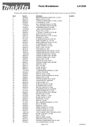
Parts Breakdown
Page 3
..., 5277NB TAPPING SCREW 4X18, 4323K HANDLE SET, 2414B SWITCH BUTTON, LS1011 TAPPING SCREW 5X50, 5037NB HANGER, 2414B PIN 6, 2414NB CHAIN, 2414B-T1 CHAIN, 2414NB COMPRESSION SPRING 4, 2414B SWITCH, HM1303B SWITCH LOCK, 2414B SWITCH LEVER COMPLETE, 2414B HANDLE SET, 2414B TAPPING SCREW 4X18, 4323K STRAIN RELIEF, HM1500B CORD GUARD, 2711 CORD (2X14X8 SJ), 2414B B. BEARING 629LLB, 4101RH INSULATION WASHER, LS1211 FIELD 115V, LC1230 T. BEARING 6202LLB, NHP1310 GEAR HOUSING (L), LC1230 GEAR COMPLETE 16-44, LC1230 B. Parts Breakdown LC1230 Products with...
..., 5277NB TAPPING SCREW 4X18, 4323K HANDLE SET, 2414B SWITCH BUTTON, LS1011 TAPPING SCREW 5X50, 5037NB HANGER, 2414B PIN 6, 2414NB CHAIN, 2414B-T1 CHAIN, 2414NB COMPRESSION SPRING 4, 2414B SWITCH, HM1303B SWITCH LOCK, 2414B SWITCH LEVER COMPLETE, 2414B HANDLE SET, 2414B TAPPING SCREW 4X18, 4323K STRAIN RELIEF, HM1500B CORD GUARD, 2711 CORD (2X14X8 SJ), 2414B B. BEARING 629LLB, 4101RH INSULATION WASHER, LS1211 FIELD 115V, LC1230 T. BEARING 6202LLB, NHP1310 GEAR HOUSING (L), LC1230 GEAR COMPLETE 16-44, LC1230 B. Parts Breakdown LC1230 Products with...
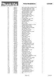
Parts Breakdown
Page 4
...SCREW M6, LS1020 PAN HEAD SCREW M6, LC1230 C.S.H. WASHER 6, HM1500 HEX. WASHER 8, 2414B PIN 16, LC1230 VISE PLATE, LC1230 LINK PLATE, LC1230 F. SCREW M5X12, 9045B GUIDE PLATE, LC1230 UNDER PLATE, LC1230 TAPPING SCREW 4X12,5477NB CAP 20, LS1013FL BASE COMPLETE, LC1230 CAP 16, LS1211 STOP RING E-8, 3901 LEVER ROD 10, LC1230 F. WASHER 10, LS0714 HEX NUT M10-17, LC1230 LEVER HOLDER COMPLETE, LC1230 F. BOLT M4X8, AF502 TORSION SPRING 38, LC1230 SAFETY COVER, LC1230 PIN 5, LC1230 COLLARD SHAFT 12, LC1230 F. WASHER 16, LS1011 HEX LOCK NUT M16-24, LS1020 DUST BOX, LC1230 RUBBER PAD, LC1230...
...SCREW M6, LS1020 PAN HEAD SCREW M6, LC1230 C.S.H. WASHER 6, HM1500 HEX. WASHER 8, 2414B PIN 16, LC1230 VISE PLATE, LC1230 LINK PLATE, LC1230 F. SCREW M5X12, 9045B GUIDE PLATE, LC1230 UNDER PLATE, LC1230 TAPPING SCREW 4X12,5477NB CAP 20, LS1013FL BASE COMPLETE, LC1230 CAP 16, LS1211 STOP RING E-8, 3901 LEVER ROD 10, LC1230 F. WASHER 10, LS0714 HEX NUT M10-17, LC1230 LEVER HOLDER COMPLETE, LC1230 F. BOLT M4X8, AF502 TORSION SPRING 38, LC1230 SAFETY COVER, LC1230 PIN 5, LC1230 COLLARD SHAFT 12, LC1230 F. WASHER 16, LS1011 HEX LOCK NUT M16-24, LS1020 DUST BOX, LC1230 RUBBER PAD, LC1230...


